Beam hardening correction in x-ray dark-field imaging

a dark-field imaging and beam hardening technology, applied in the direction of material analysis using wave/particle radiation, instruments, applications, etc., can solve the problems of incorrect results, artifacts, and inability to accurately assign all attenuation to a single material, and achieve the effect of robust overall processing

Active Publication Date: 2021-09-14
KONINKLJIJKE PHILIPS NV
View PDF6 Cites 8 Cited by
  • Summary
  • Abstract
  • Description
  • Claims
  • Application Information

AI Technical Summary

Benefits of technology

[0030]One approach on carrying out such calibration step includes the acquiring of a calibration scan with no sample in the beam at all, a further calibration scan with different thicknesses of a first calibration material (or reference material) and a yet further calibration scan with different thicknesses of a second calibration material (or reference material). Alternatively, such calibration may be done in a combined scan, where portions of the field of view include no sample, different thicknesses of the first calibration material, different thicknesses of the second calibration materials, and different combinations of the first and second material. Furthermore, it is also possible to provide, rather than one scan for different thicknesses of a material, different scans of the material, each with a different thickness. Provided that the detector area is sufficiently homogeneous, the different calibrations may be performed in a single imaging (or scanning) process. The more information is obtained by the calibration in total, the more robust the overall processing will be.

Problems solved by technology

It was found by the inventors that the improper attribution of all attenuation to a single material leads, in cases where there are materials, like bone and soft-tissue, present with different spectral properties, to incorrect results and to artifacts.

Method used


Image

  • Beam hardening correction in x-ray dark-field imaging
  • Beam hardening correction in x-ray dark-field imaging
  • Beam hardening correction in x-ray dark-field imaging

Examples


first embodiment

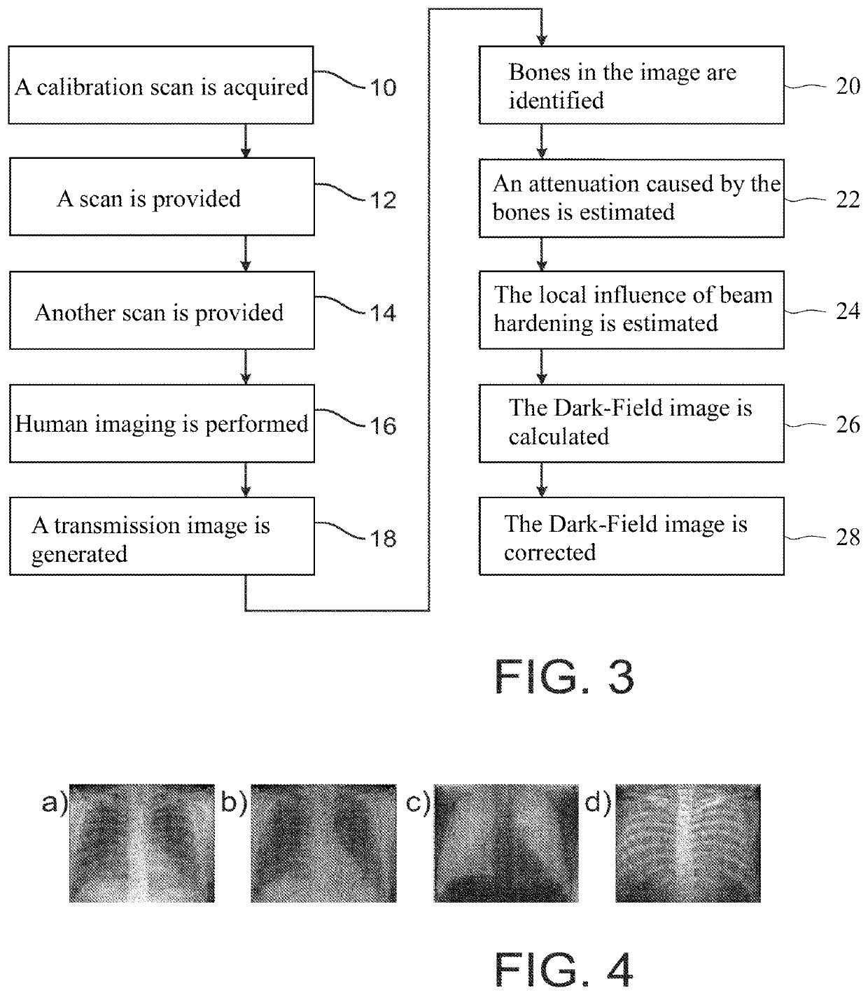
[0057]FIG. 3 shows a flow diagram illustrating a method of correcting for beam hardening according to the present invention.

[0058]In the embodiment illustrated in FIG. 3, before human imaging is performed a calibration scan is acquired in step 10 without anything in the beam.

[0059]Further, in steps 12 and 14, two scans with different thicknesses of two different materials in the beam, respectively, are provided. The two scans are performed separately. Here, the second calibration material has similar absorption properties to the soft tissue (e.g. plastic POM) and the first calibration material has spectral absorption properties similar to the bones (e.g. aluminum).

[0060]Subsequently, human imaging is performed (step 16) and the transmission image is generated (step 18). Based on this transmission image the bones in the image are identified (step 20) and the attenuation caused by the bones is estimated (step 22). Currently available software can generate such bitmaps with the require...

second embodiment

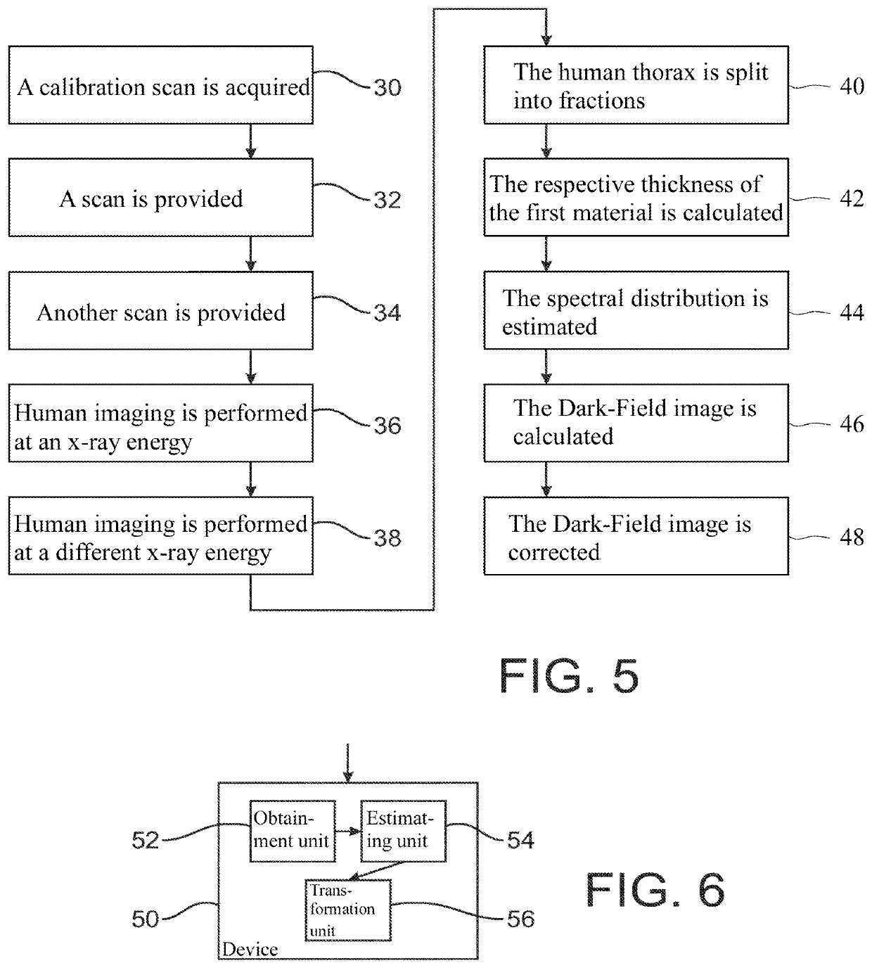
[0080]FIG. 5 shows a flow diagram illustrating a method of correcting for beam hardening according to the present invention.

[0081]Several steps of this embodiment correspond to those discussed above as to the first embodiment.

[0082]Specifically, steps 30 to 34 including the acquisition of a blank calibration scan and calibration scans for different thicknesses of the first and second calibration materials correspond to steps 10 to 14, respectively, which are discussed above.

[0083]Deviating from the first embodiment, however, subsequently, human imaging is performed at two different x-ray energies (e.g. 56 kVp and 120 kVp) (steps 36 and 38) and the transmission images are generated (it is noted here that one of the scans may be a pure transmission scan, e.g. the 120 kVp image, and can be obtained with detuned gratings, or still tuned gratings but only one x-ray shot). Based on these transmission images, the human thorax can be split into the fraction that can be approximated by POM (...


PUM


Abstract

The invention relates to beam hardening correction in X-ray Dark-Field imaging of a subject including a first material and a second material, the first and second material having different beam hardening properties. As the X-ray imaging data includes information on the internal structure of the imaged subject, such information may be used, together with appropriate calibration data to identify the beam hardening contributions occurring in the imaged area of the subject, so to allow for a correction of artifacts due to beam hardening in X-ray Dark-Field imaging.

Description

FIELD OF THE INVENTION[0001]The invention relates to beam hardening correction in X-ray Dark-Field imaging of a subject including a first material and a second material, the first and second material having different beam hardening properties.BACKGROUND OF THE INVENTION[0002]There is a paper “Data processing and image reconstruction methods for pixel detectors” by Jan Jakubek (Nuclear Instruments and Methods in Physics Research A 576 (2007) 223-234 disclosing that semiconductor single-particle-counting pixel detectors offer many advantages for radiation imaging: high detection efficiency, energy discrimination, noiseless digital integration (counting), high frame rate and virtually unlimited dynamic range. All these properties allow to achieve high quality images. Examples of transmission images and 3D tomographic reconstruction using X-rays and slow neutrons are presented demonstrating effects that can affect the quality of images. A number of obstacles can limit detector performan...

Claims


Application Information

Patent Timeline
Patent Type & Authority Patents(United States)
IPC IPC(8): A61B6/00G01T7/00
CPCA61B6/583A61B6/4241A61B6/482A61B6/484A61B6/5258G01T7/005A61B6/4291G01N2223/206G01N2223/423
Inventor YAROSHENKO, ANDRIYMAACK, HANNS-INGOKOEHLER, THOMASDE MARCO, FABIOGROMANN, LUKAS BENEDICTKONSTANTIN, WILLERNOEL, PETER
Owner KONINKLJIJKE PHILIPS NV
Why Eureka
Try Eureka