

Fabrication Method For Electronic System Modules
- Summary
- Abstract
- Description
- Claims
- Application Information
AI Technical Summary
Benefits of technology
Problems solved by technology
Method used
Image

Examples
second embodiment
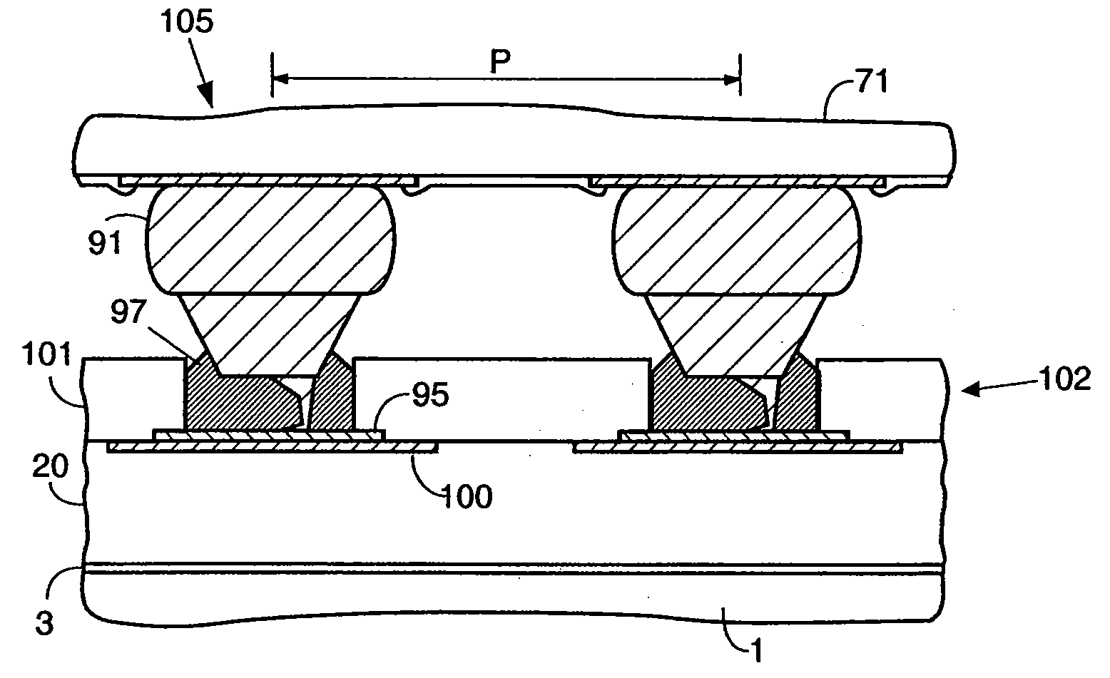
[0071] In FIG. 10A interconnection circuit 20 is shown, including flat I / O pads 100, coated with metallization 95 as previously described. Again, glass carrier 1 is present for dimensional stability. In FIG. 1OB a planarizing layer 101 of non-photo-definable polymer such as BCB is formed on top of interconnection circuit 20, at a thickness of approximately 15 microns when cured. Polymer layer 101 is masked and etched using known dry etching techniques to create openings (wells) 102 above the pads. The diameter of the wells is approximately 34 microns in the preferred embodiment. The openings preferably have vertical walls as shown, providing maximum resistance to shear forces in the final assembly (with chips attached). Vertical walls are not generally producible using photo-defined polymers such as photo BCB, and this is why dry etching is used, preferably with an anisotropic etching characteristic as is known in the art. Polymer layer 101 forms the solder paste mask and is typical...
first embodiment
[0072] It is a primary goal of the current invention to provide flip chip assemblies that can be reworked when a defective chip needs replacement. The process should be simple and effective, and robust enough to perform as many times as may be necessary. Consequently, it is important to choose a solder composition that does not significantly dissolve the stud bump material, does not form brittle intermetallic compounds, and for which the melting point is not significantly increased during assembly or rework cycles. Gold is the preferred material for the stud bumps. As previously described, an example of a solder material that is compatible with gold stud bumps and the flip chip bonding methods proposed herein is indium-based solder Indalloy #290, obtainable from Indium Corporation of America, Utica, N.Y. The amount of paste in a well is approximately 1.5×10⁻⁸ gm in the second preferred embodiment, at a material cost of approximately US$3.48 per gram. For either method of fabricating...
PUM
| Property | Measurement | Unit |
|---|---|---|
| Dielectric polarization enthalpy | aaaaa | aaaaa |
| Adhesion strength | aaaaa | aaaaa |
| Flexibility | aaaaa | aaaaa |
Abstract
Description
Claims
Application Information