Heat Exchange Laminate

Active Publication Date: 2008-02-21
OXYCOM BEHEER BV
View PDF14 Cites 10 Cited by
  • Summary
  • Abstract
  • Description
  • Claims
  • Application Information

AI Technical Summary

Benefits of technology

[0012]According to the present invention, an improved heat exchange laminate is provided comprising a formable carrier layer at least partially covered with a flexible liquid retaining layer having an open structure such that in use, a heat exchange medium can directly contact the carrier layer through the open structure of the liquid retaining layer. By forming such a laminate of two layers, desired properties such as the spatial distribution of the liquid retaining layer, can be imparted to the heat exchange laminate prior to forming. The laminate may then be conveniently formed into any desired shape by known manufacturing procedures. By providing the liquid retaining layer with an open structure, the ability of the heat exchanger to transfer both thermal heat and latent heat to a fluid medium flowing over it is enhanced. The open structure may comprise spaces between the fibres of a fibrous material forming the liquid retaining layer. Such a fibrous material may be a woven or non-woven layer having an open structure. In particular, knitting or other knotting techniques have been found extremely effective in producing an open structure having sufficient height to buffer a considerable quantity of liquid.
[0020]According to a particular advantage of the present laminate, the heat exchange element may comprise a heat exchange laminate having an open structured liquid retaining layer on both surfaces of the carrier layer. Such a heat exchange element is extremely versatile for use in evaporative type heat exchangers and dew-point coolers. Because of the open structure, both sides of the laminate can function either as a wet side or as a dry side, depending upon the direction of flow and the supply of water. This allows the use of a dew-point cooler as a heat recovery element during e.g. cold periods and also permits humidification of the incoming air stream. In this context, a particular advantage of the laminate according to the invention lies in the ability of the water retaining layer to retain and transport water formed by condensation on the cooling side of such a heat recovery element. In the past, such water has tended to form as droplets which could cause choking or restriction of the heat exchange elements. The presence of a liquid retaining layer according to the present invention ensures that a tin film of water is retained, thus optimising heat transfer, while excess water is drained away. The recovered water may subsequently be supplied to the heated side for humidification purposes.
[0023]In an advantageous embodiment of the method the laminate may be attached to a first surface of a membrane for heat transfer thereto. If the laminate is corrugated into fins, the base of each fin may be attached to the membrane preferably by adhesive. Prior art heat exchangers have generally been formed by soldering and brazing techniques. According to an important development of the present invention, the joining of the fins to the membrane by adhesive may permit a rapid, inexpensive and light assembly. In particular, heat and pressure activated adhesives are favoured which may be provided as an integral part of the laminate or the membrane prior to forming and joining.

Problems solved by technology

In general, relative humidity of less than 50% has been recognised as being undesirable.
Many attempts have been made to realise such cycles but practical considerations have caused great difficulties in approaching the dew point over most temperature ranges.
Whilst not wishing to be bound by theory, applicant believes that successful cooling to the dew point can only be achieved in this type of device by providing incremental and repeated alternate thermal heat transfer followed by latent heat transfer.
A smooth metal surface such as aluminium has high water activity and will thus easily give up water.
Unfortunately however, it is not good at retaining water and cannot provide an effective buffer of water for evaporation.
Although such a layer has been found to have excellent water activity and water buffering characteristics as a result of its open structure, it nevertheless displays certain disadvantages: it is relatively heavy; it is susceptible to flaking and powdering especially if the carrier layer on which it is formed is subjected to shook or bending; and it is inconvenient to apply in a clean manufacturing environment.
In particular, the cement coating must be applied to the formed product, since once coated, the material forming the heat exchanger can no longer be formed, Applying a layer of a desired thickness distribution to a complex shape is difficult and the prior art cement coatings have been found to show undesirable thickness variation.

Method used


Image

  • Heat Exchange Laminate
  • Heat Exchange Laminate
  • Heat Exchange Laminate

Examples


Embodiment Construction

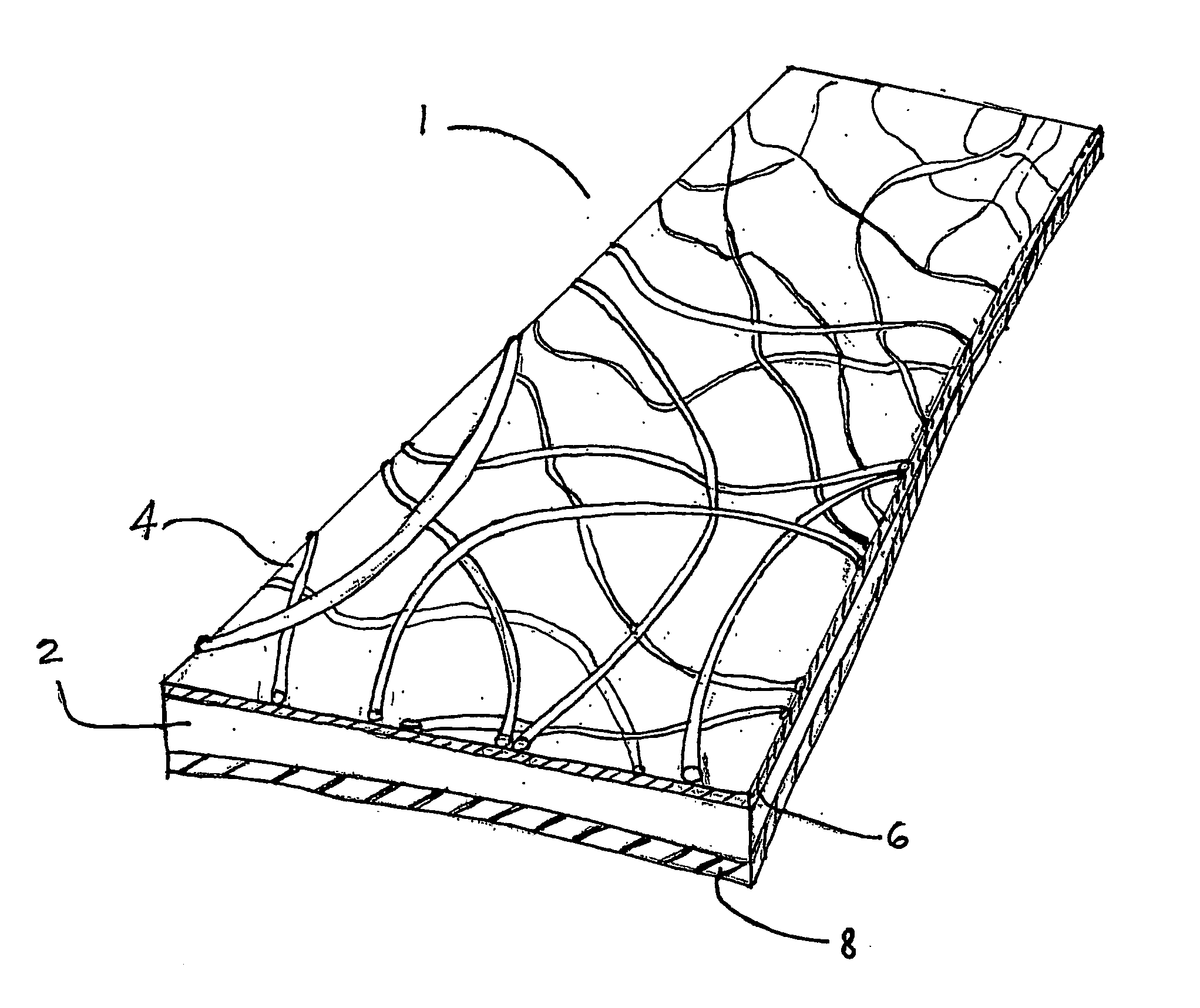
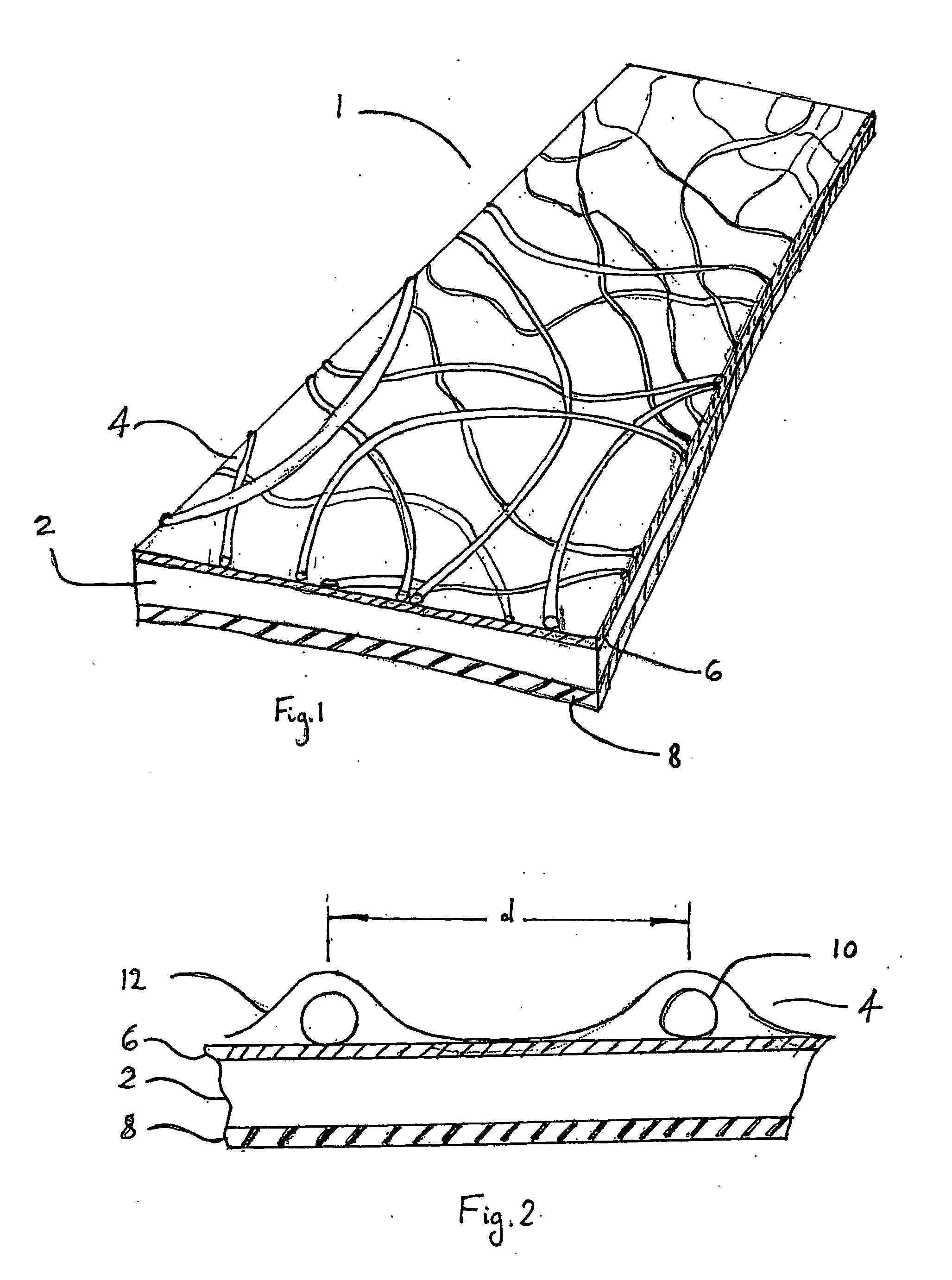
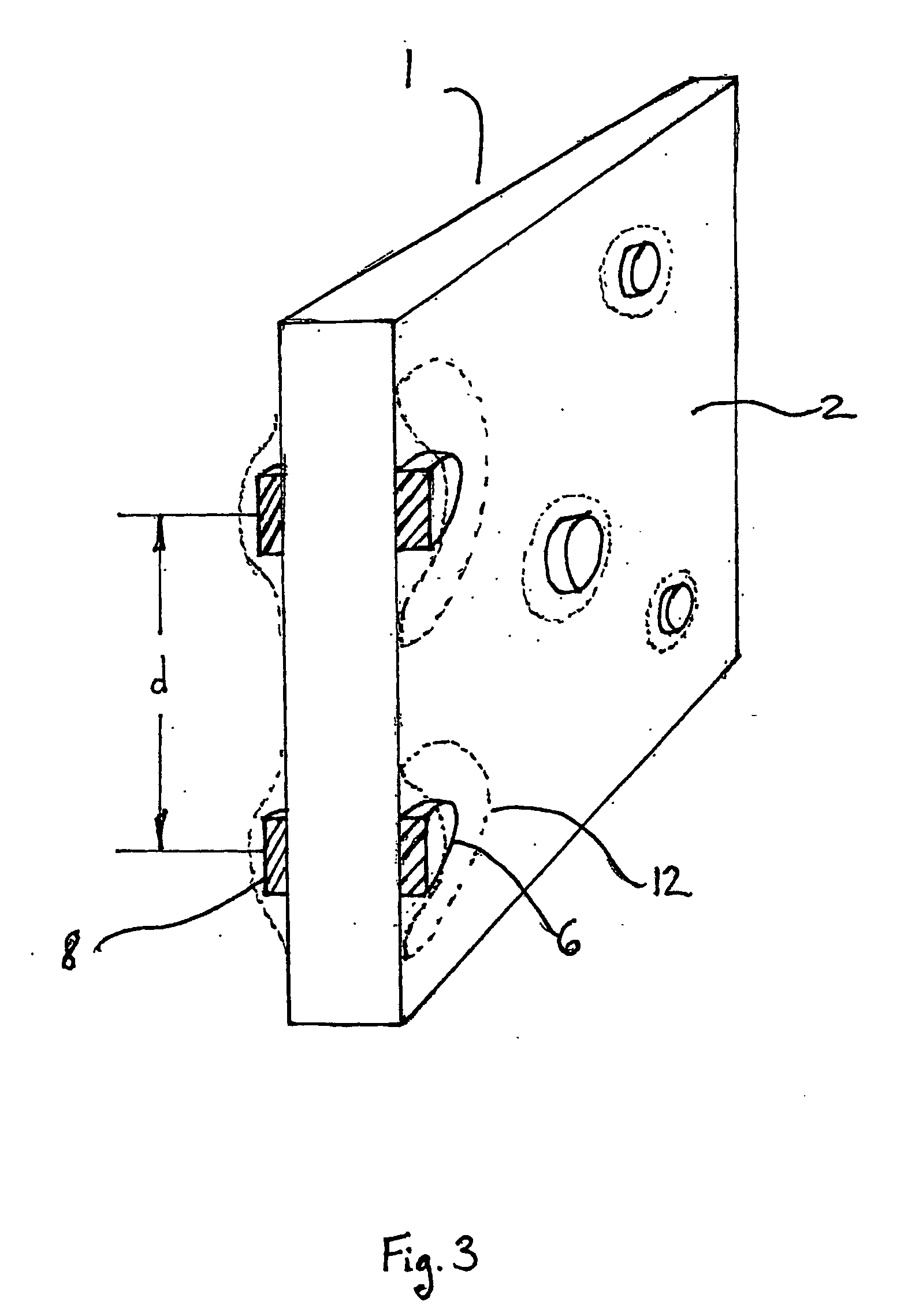
[0032]According to FIG. 1, there is depicted a section of a heat exchange laminate 1 illustrating the individual layers. Laminate 1 comprises a carrier layer 2 covered over its first surface by a liquid retaining layer 4. A first adhesive 6 is provided between the carrier layer and the liquid retaining layer. A second adhesive 8 is also provided on the second surface of the carrier layer 2. In this embodiment, the presence of second adhesive 8 is optional and its function will be described in further detail below.

[0033]Carrier layer 2 is preferably formed of soft annealed aluminium having a thickness of approximately 70 microns. This material has been found to be extremely advantageous as it is light, easily formable and has good conductivity. The aluminium is provided on both surfaces with a primer (not shown) to ensure adequate bonding with the adhesives 6, 8. The primer is preferably a PVC based primer and may be coloured to provide a desirable appearance to the laminate 1. Furth...


PUM

PropertyMeasurementUnit
Thicknessaaaaaaaaaa
Flexibilityaaaaaaaaaa
Electrical conductoraaaaaaaaaa

Abstract

A heat exchange laminate comprises a formable carrier layer at least partially covered with a flexible liquid retaining layer having an open structure. By forming such a laminate of two layers, desired properties such as the spatial distribution of the liquid retaining layer, can be imparted to the heat exchange laminate prior to forming. The laminate may then be conveniently formed into any desired shape by known manufacturing procedures for incorporation into a heat exchanger. The laminate may be used to cool a first fluid by evaporation of a liquid into a second fluid operating at or near its saturation point.

Description

BACKGROUND OF THE INVENTION[0001]1. Field of the Invention[0002]The present invention relates to a laminate for a heat exchanger and more particularly to a laminate comprising a liquid retaining layer for use in evaporative type heat exchangers. The invention also relates to a heat exchanger formed from the laminate and to a method of producing such a heat exchanger.[0003]2. Description of the Related Art[0004]There are a number of situations in which heat exchange in combination with the evaporation of a liquid may be desirable. One such situation is in the humidification of dry air. When air is heated, its ability to carry moisture increases and thus its relative humidity decreases if no further moisture is added. In cold periods, heating installations providing warm air to a building may require some form of humidification in order to compensate for this decrease in relative humidity. In general, relative humidity of less than 50% has been recognised as being undesirable. One way...

Claims


Application Information

Patent Timeline
IPC IPC(8): F28D3/04B23P15/26F24F1/0007F24F5/00F28D5/00F28F3/02F28F13/18
CPCF24F5/0035F24F2001/0092F28D5/00F28F3/025Y10T29/49359F28F13/18Y02B30/545Y02B30/52F28F3/027F24F1/0007Y02B30/54F24F5/00F24F1/00F28F3/00
Inventor REINDERS, JOHANNES ANTONIUS MARIA
Owner OXYCOM BEHEER BV
Why Eureka
Try Eureka