Washing machine and pulley for washing machine

a technology for washing machines and pulleys, applied in mechanical equipment, gearing, hoisting equipment, etc., can solve the problems of increasing the cost of a member, the drum needs to be driven high, and the vibrations transferred to the drum may be reduced, so as to suppress the increase of noise, improve the rigidity of the pulley, and suppress the weight of the pulley from increasing

Active Publication Date: 2021-09-28
SAMSUNG ELECTRONICS CO LTD
View PDF12 Cites 0 Cited by
  • Summary
  • Abstract
  • Description
  • Claims
  • Application Information

AI Technical Summary

Benefits of technology

[0008]Since vibrations generated from the motor are transferred to the pulley, the drum, and further, a case of the washing machine through the endless belt, relatively large noises are generated due to the vibrations from the motor during the dehydration in which the motor rotates at high speed. At this time, in a case of the above-described pulley, since a resonance frequency of the pulley has a value close to a value of a rotation frequency of the motor during the dehydration, amplitudes of the vibrations transferred to the pulley are amplified, and thus noises increase.
[0028]According to a washing machine of the present invention, since the rigidity of a pulley can be improved while suppressing a weight of the pulley from increasing, excessive noises due to resonance can be reduced.

Problems solved by technology

However, the pulley includes an inner pulley of a disk shape having a shaft hole at a center thereof, an outer pulley having an annular plate shape and disposed around the inner pulley, and a vibration absorption member such as rubber inserted into a gap between the inner pulley and the outer pulley, and the vibration absorption member damps and absorbs vibrations transferred to the pulley.
Although a drum is controlled to rotate at low speed during washing or rinsing, since a large amount of water is left in the drum, the drum needs to be driven with high torque, and although the drum is drained during dehydration and thus may be driven with low torque, since the drum is driven by a centrifugal force, the drum needs to be rotationally driven at high speed.
Like a pulley disclosed in Japanese Laid-Open Patent Publication No. 11-114282, when a vibration absorption member is mounted on the pulley, vibrations transferred to a drum may be reduced, however, when the vibration absorption member is separately mounted, new problems such as an increase of costs for a member, lowered rigidity and durability of the pulley, and the like occur.
However, when widths or thicknesses of arms are increased to increase the rigidity of the pulley, since a weight of the pulley increases, and thus the costs for a member increase, the advantage is hindered.

Method used


Image

  • Washing machine and pulley for washing machine
  • Washing machine and pulley for washing machine
  • Washing machine and pulley for washing machine

Examples


first embodiment

[0063]When designing a drum pulley 20, an analysis for a structure of an arm 23 was performed by a finite element method (FEM). A model used in the analysis is shown in FIGS. 7A and 7B. FIG. 7A shows a conventional model (a reference example model M1), and FIG. 7B shows a model to which an embodiment of the present invention is applied (an embodiment model M2).

[0064]The reference example model M1 was provided to have a shape having a cross-section uniform from a base end (a portion connected to a boss 22) of the arm 23 to a front end (a portion connected to an outer wheel 21) of the arm 23, and the embodiment model M2 was provided to have a shape having a uniform cross-sectional portion 25 in a base end side of the arm 23, and a variable cross-sectional portion 24 in a front end side of the arm 23. A boundary between the uniform cross-sectional portion 25 and the variable cross-sectional portion 24 was provided to be 30 mm apart from the base end of the arm 23.

[0065]In this analysis...

second embodiment

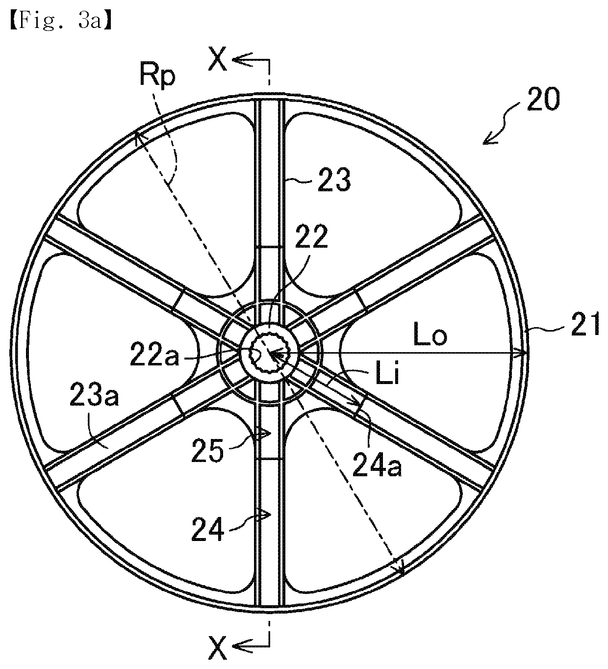
[0072]In an analysis for the embodiment model M2, a relation between a proportion and rigidity of the variable cross-sectional portion 24 of the arm 23 was investigated. Specifically, a weight, a maximum width, and a length were the same as those in the first embodiment, and as shown in FIG. 3A, by varying a ratio Li / Lo (%) which is a ratio of a length Li from a center C to an end portion of the variable cross-sectional portion 24 located at the boss 22 (an end portion 24a adjacent to the boss), with respect to a length Lo from the center C to a periphery of the outer wheel 21, an optimum state in which a displacement amount of a front end of the arm 23 is minimized at each of the varied ratios Li / Lo was obtained. A result is shown in FIG. 10. Further, a vertical axis shows a displacement amount reduction rate of the front end (% with respect to the reference example model M1).

[0073]A displacement amount reduction effect was further found when the ratio Li / Lo became smaller (the uni...

third embodiment

[0074]Further, the influence on rigidity of the variable cross-sectional portion 24 according to a change amount of a height of the variable cross-sectional portion 24 was also investigated. Under conditions the same as the conditions in the second embodiment, at ratios Li / Lo of the variable cross-sectional portion 24 (30%, 50%, 70%), as shown in FIG. 7B, by varying a ratio Ho / Hi, which is a ratio of a height Ho of an end portion of the variable cross-sectional portion 24 located at the outer wheel 21 (an end portion 24b adjacent to an outer wheel), with respect to a height Hi of an end portion 24a adjacent to the boss, to greater than or equal to 30%, an optimum state in which a displacement amount of a front end of the arm 23 is minimized at each of the ratios Ho / Hi was obtained. A result is shown in FIG. 11. Further, like the second embodiment, a vertical axis shows a displacement amount reduction rate of the front end (% with respect to the reference example model M1).

[0075]A di...


PUM


Abstract

By improving the rigidity of a pulley while suppressing a weight of the pulley from increasing, excessive noises due to resonance can be reduced. A washing machine 1 includes a drum 9 rotatably disposed in the water tub 5. The washing machine 1 has a motor to rotationally drive a pulley 20, which is fixed to the drum 9, via an endless belt 13. The pulley 20 has a plurality of arms 23 radially extend from the boss 22 to support an outer wheel 21. The arm 23 has a variable cross-sectional portion 24 in which a section modulus against bending in an axial direction gradually decreases from the boss 22 to the outer wheel 21.

Description

CROSS-REFERENCE TO RELATED APPLICATIONS AND CLAIM OF PRIORITY[0001]This application is a 371 National Stage of International Application No. PCT / KR2016 / 013005 filed Nov. 11, 2016, which claims priority to Japanese Patent Application No. 2015-223243 filed Nov. 13, 2015, the disclosures of which are herein incorporated by reference in their entirety.BACKGROUND1. Field[0002]The present invention relates to a technology for suppressing noises and vibrations generated from a pulley directly mounted on a drum.2. Related Art[0003]As a pulley directly mounted on a drum, a pulley having a shape in which a plurality of arms radially extend from a boss at a center to support an outer wheel, is, for example, disclosed in European Patent Application Publication specification (EP0823503A2). However, the arms of the pulley form a shape of a band plate having a constant thickness in an axial direction.[0004]Further, a pulley configured to prevent vibrations and noises of a washing machine is disclo...

Claims


Application Information

Patent Timeline
Patent Type & Authority Patents(United States)
IPC IPC(8): D06F37/22F16H55/36F16H55/40D06F37/20D06F37/04D06F37/30F16H7/02D06F58/08D06F37/36
CPCD06F37/206D06F37/04D06F37/30F16H7/02F16H55/36D06F37/22D06F37/36D06F58/08F16H2055/366D06F37/40
Inventor SHIMADA, YOSHINARIMORI, KAZUSHINAKASHIMA, TAKAHIRO
Owner SAMSUNG ELECTRONICS CO LTD
Why Eureka
Try Eureka