
Methods for creating a zinc-metal oxide layer in metal components for corrosion resistance

a technology of zinc metal oxide and metal components, which is applied in the direction of manufacturing tools, heat treatment equipment, furnaces, etc., can solve the problems of metal, steel or alloy being subject to such corrosion, fouling, and efficiency loss, and metal corrosion in water cooled systems is a major reliability factor

Active Publication Date: 2021-10-05
ELECTRIC POWER RES INST INC
View PDF15 Cites 0 Cited by
  • Summary
  • Abstract
  • Description
  • Claims
  • Application Information

AI Technical Summary

Benefits of technology

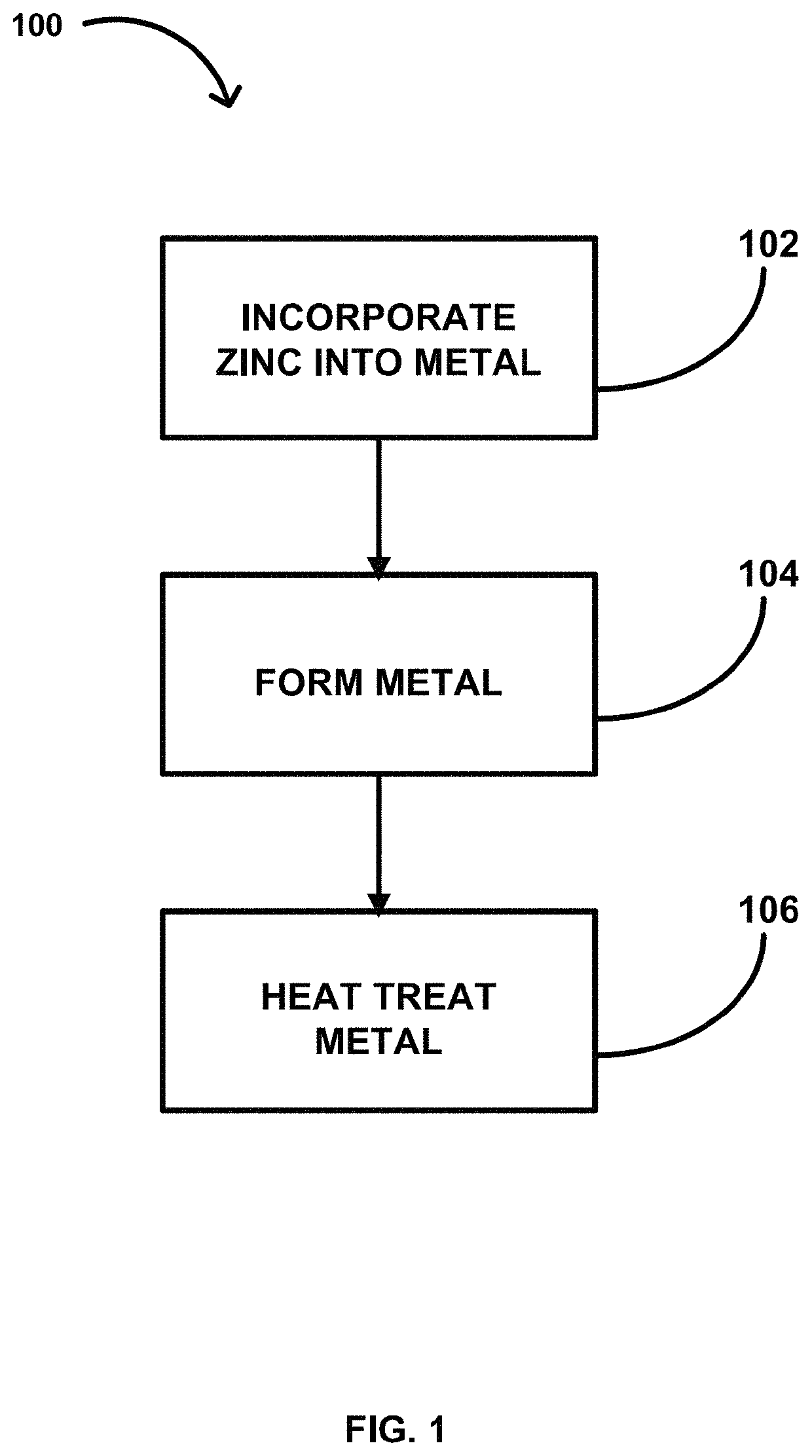
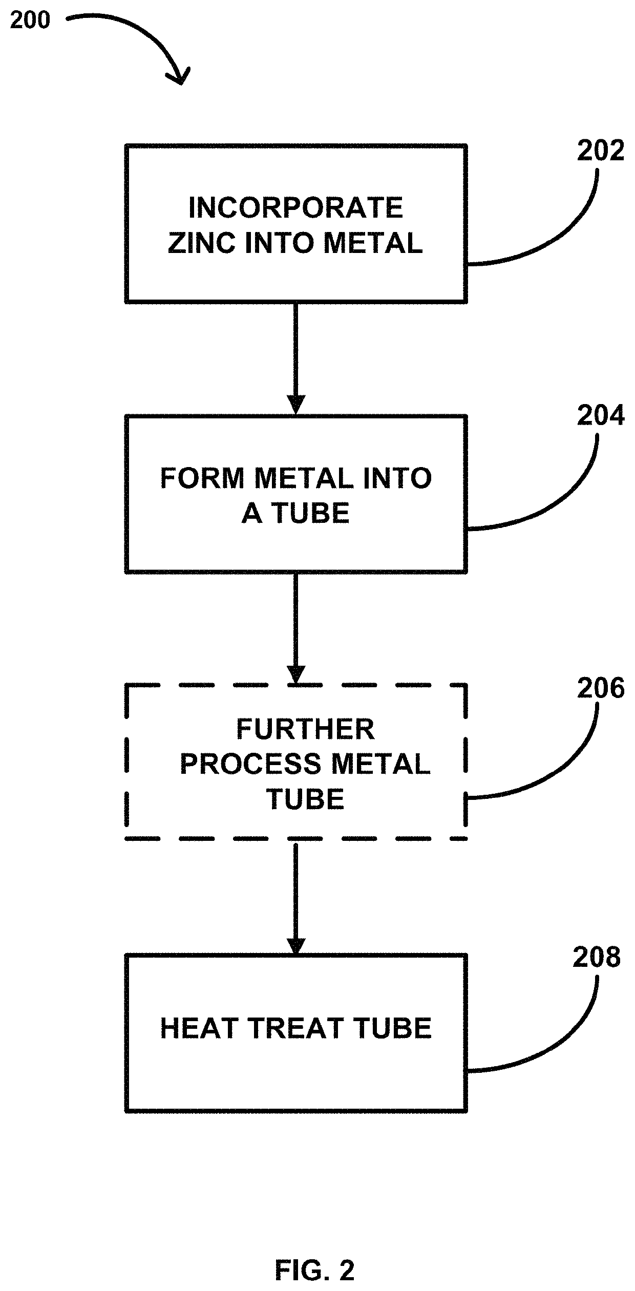
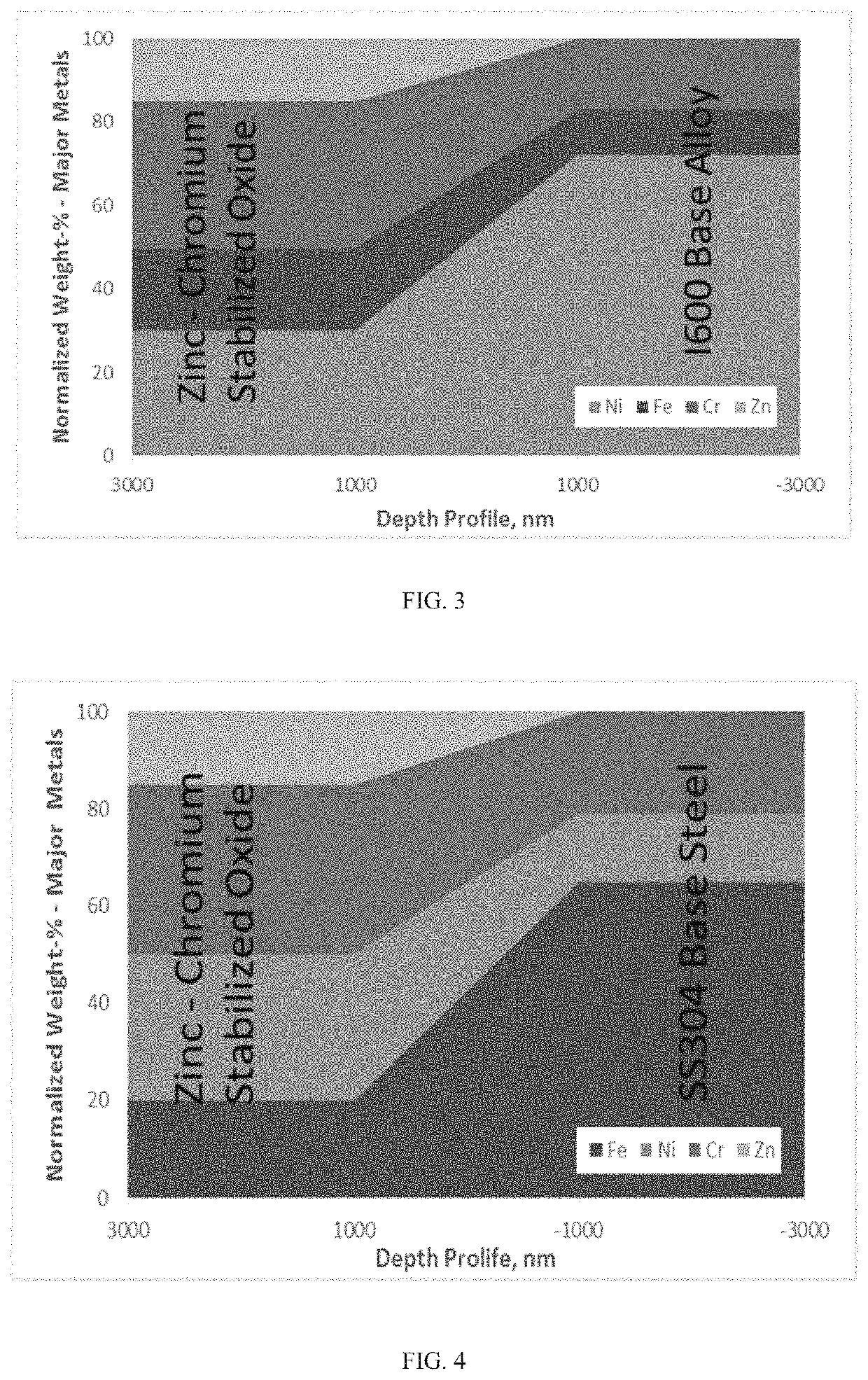
The present invention provides a method for manufacturing a finished metal object or product with a corrosion resistant layer on its surface. This layer is formed during the manufacturing process and is more stable and long-term viable than a similar layer formed after manufacture and readiness for service. By incorporating zinc into the metal object or product and creating a zinc-metal oxide or zinc-mixed metal oxide layer, corrosion of the underlying metal is reduced, which increases asset reliability and plant availability and efficiency. This method can be used for manufacturing components of power plants, such as steam generators, heat exchangers, and moisture separators, and can also be applied to already in-service components to extend their lifetimes and reduce metal releases.

Problems solved by technology

In the power generating industry, metal corrosion in water cooled systems is a major reliability factor.
Any metal, steel, or alloy is subject to such corrosion.
The released material is often deposited elsewhere in the system, such as in low-flow regions or on heat transfer surfaces, causing fouling and efficiency losses.
Unfortunately, such preconditioning does not provide a stable, long-lasting corrosion resistant film that avoids metal release during normal operation.
Additionally, plants have only a limited amount of time available for such preconditioning and cannot devote thousands of exposure hours that may otherwise be necessary to establish a stable film on most metal surfaces.

Method used


Image

  • Methods for creating a zinc-metal oxide layer in metal components for corrosion resistance
  • Methods for creating a zinc-metal oxide layer in metal components for corrosion resistance
  • Methods for creating a zinc-metal oxide layer in metal components for corrosion resistance

Examples


Embodiment Construction

[0019]The present invention is described below with reference to the accompanying Figures. While the invention will be described in conjunction with particular embodiments, it should be understood that the invention includes different embodiments and can be applied to a wide variety of applications. Accordingly, the following description is exemplary and is intended to cover alternatives, modifications, and equivalents within the spirit and scope of the invention. Further, the various embodiments may be described by use of the terms “preferably,”“for example,” or “in one embodiment,” but this characterization should not be viewed as limiting or as setting forth the only embodiments of the invention, as the invention encompasses other embodiments that may not be specifically recited in this description. Further, the use of the terms “invention,”“present invention,”“embodiment,” and similar terms throughout this description are used broadly and are not intended to mean that the invent...


PUM

PropertyMeasurementUnit
corrosion resistantaaaaaaaaaa
shapeaaaaaaaaaa
corrosionaaaaaaaaaa

Abstract

The present invention provides a method for manufacturing a finished metal object or product having a corrosion resistant layer integral to or within a top portion of at least one of its surfaces that would be exposed to a corrosive environment. In one embodiment, the method for manufacturing is directed to a finished metal tubing product having a corrosion resistant layer within its inside surface that is exposed to a fluid and wherein the corrosion resistant layer is a zinc-metal oxide layer, such as a zinc-chromium oxide layer, or a zinc-mixed metal oxide layer. In addition to methods of manufacturing, the present invention provides finished metal objects or products having a corrosion resistant layer integral to or within a top portion of at least one surfaces that would be exposed to a corrosive environment.

Description

CROSS REFERENCE TO RELATED APPLICATIONS[0001]This application claims the benefit of U.S. Provisional Application No. 62 / 247,945, filed Oct. 29, 2015, the content of which is incorporated by reference herein in its entirety.BACKGROUND OF THE INVENTION[0002]Field of the Invention[0003]The present invention in its various embodiments provides a method for manufacturing a corrosion resistant layer integral to a top portion of a metal surface of a metal object or product to reduce corrosion of the metal surface and release of metal species. In particular, the present invention provides a method for manufacturing a finished metal object or product having a stabilized zinc-metal oxide or zinc-mixed metal oxide layer integral to an exposed surface, such as the interior surface of a metal tube, to reduce corrosion and release of metals from the metal. The present invention in its various embodiments also provides finished metal objects or products having an integral corrosion resistant layer...

Claims


Application Information

Patent Timeline
Patent Type & Authority Patents(United States)
IPC IPC(8): C23C10/00C23C8/10C23C10/08C23C10/14C23C10/36C23C10/52C23C10/54C23C8/14C23C8/02B21B21/00B21C1/22C21D6/00C21D9/00C21D9/08C23C10/60C23C22/53B21C1/00
CPCC23C10/08B21B21/00B21C1/22C21D6/004C21D9/0068C21D9/08C23C8/02C23C8/14C23C10/14C23C10/36C23C10/52C23C10/54C23C10/60B21C1/003C23C10/16
Inventor RIDDLE, JOHN MORRISONGREGORICH, CAROLA ANNEMARIEWELLS, DANIEL M.
Owner ELECTRIC POWER RES INST INC
Learn More