Use of isolation condenser and/or feedwater to limit core flow, core power, and pressure in a boiling water reactor

a technology of isolation condenser and feedwater, which is applied in the direction of nuclear reactors, greenhouse gas reduction, nuclear elements, etc., can solve the problems of cooling water to boil, increased core voiding, and limited ability of cold condensate to directly condense steam in the downcomer region of the boiling water reactor to achieve the effect of reducing reducing the peak pressure, and increasing the effectiveness of the isolation condenser system

Active Publication Date: 2021-10-05
GE HITACHI NUCLEAR ENERGY AMERICAS
View PDF9 Cites 0 Cited by
  • Summary
  • Abstract
  • Description
  • Claims
  • Application Information

AI Technical Summary

Benefits of technology

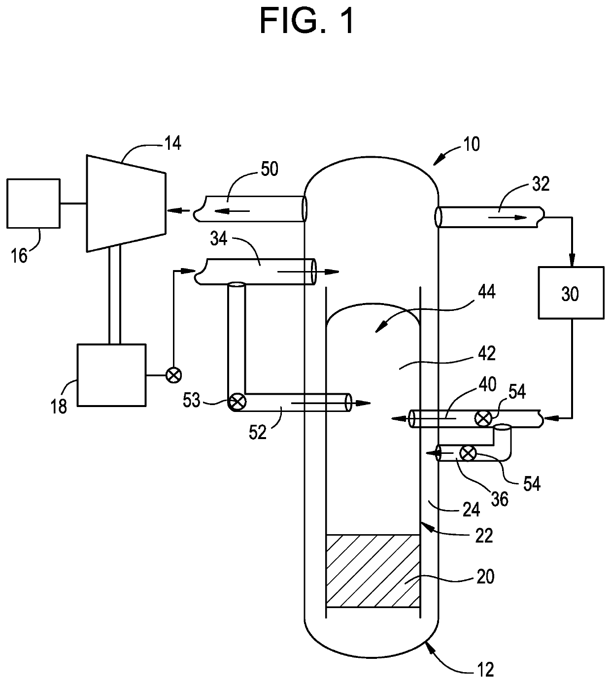
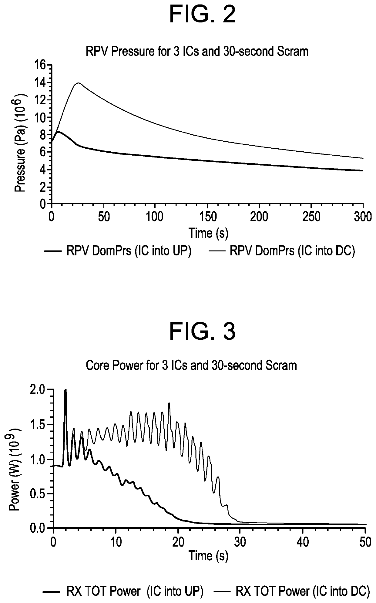
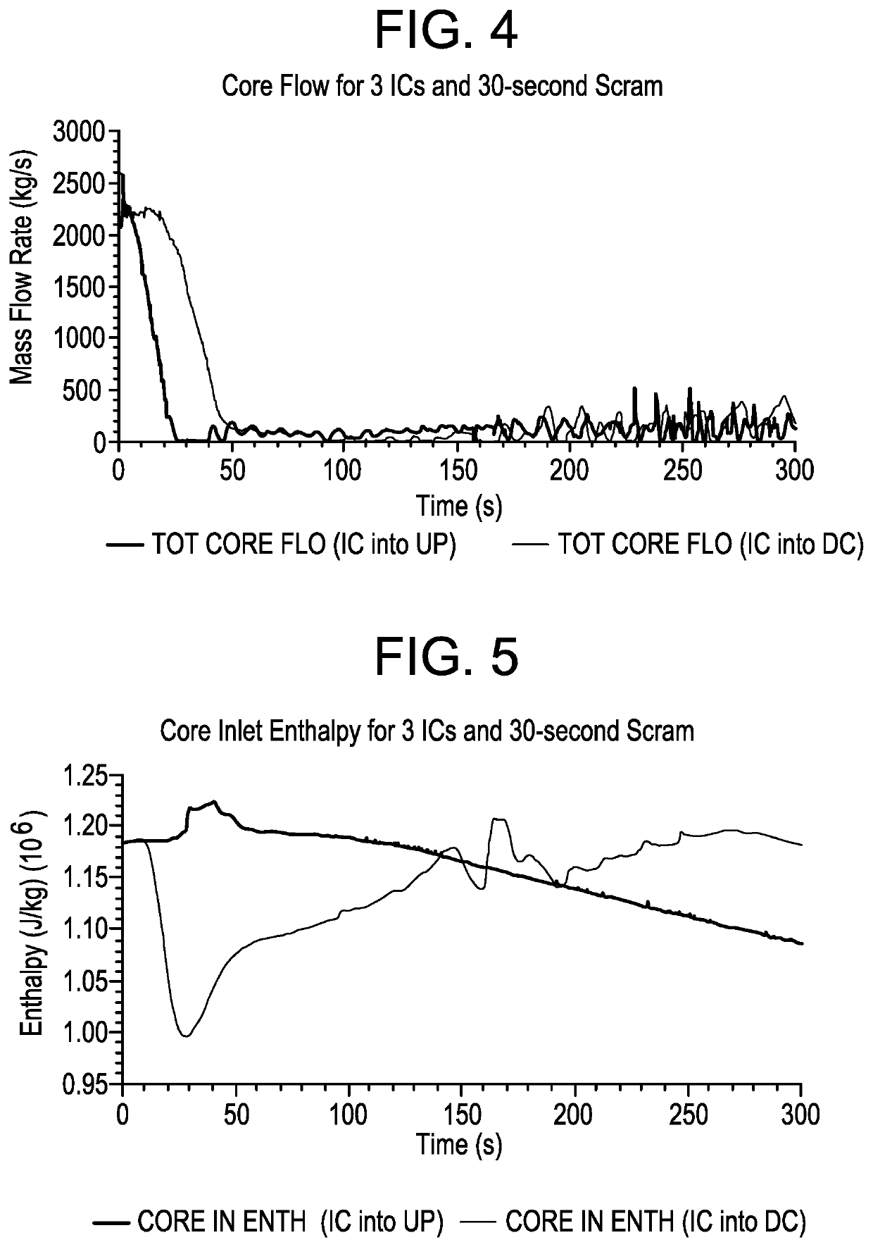
[0010]The isolation condenser system lowers reactor pressure vessel pressure following an isolation event. Any increase in core power that results from the condensate return into the downcomer region of the reactor pressure vessel reduces the effectiveness of the isolation condenser system. The reactor pressure vessel pressure increase can be unacceptably large especially when the isolation event occurs concurrent with a failure or delay in scram (reactor shutdown) such as in an anticipated transient without scram. Return of the isolation condenser system condensate into the region above the core, on the other hand, dramatically increases the effectiveness of the isolation condenser system and substantially lowers the peak pressure that will occur. This lowering of the pressure provides additional time for an alternate slower scram mechanism to function during an anticipated transient without scram scenario where the faster primary scram mechanism has failed or was severely degraded.
[0011]The isolation condenser system condensate is returned to the reactor pressure vessel of the boiling water reactor inside the core barrel above the core rather than into the downcomer. This increases isolation condenser system effectiveness and makes it possible to greatly reduce the magnitude of the pressure increase that would otherwise occur consequently, the opening of safety relief valves can be avoided which retains fluid inventory in the reactor pressure vessel. The need for high pressure emergency core cooling systems can be eliminated because the water inventory is not being depleted. The reactor pressure vessel and attached piping can be designed for a lower pressure. Containment size can be decreased, and / or the design pressure and temperature reduced. Dynamic loads to the containment caused by blowing down of the reactor pressure vessel through relief valves can be eliminated. Mitigation of the anticipated transient without scram by a slower alternate scram mechanism becomes possible so that a backup system for reactivity control via injection of a neutron-observing fluid; i.e., standby liquid control system can be eliminated.

Problems solved by technology

Heat is produced by nuclear fission in the reactor core, and this causes the cooling water to boil, producing steam.
The forced recirculation head from the recirculation pumps is very useful in controlling power, however, and allows higher power levels that would not otherwise be possible.
Return of cold condensate to the downcomer region of a boiling water reactor has limited ability to directly condense steam because the condensate return occurs below the liquid mixture level.
Return of isolation condenser system condensate into the lower density region above the core reduces the manometer effect, reduces core flow, causes core voiding to increase, and consequently the core power decreases.
Any increase in core power that results from the condensate return into the downcomer region of the reactor pressure vessel reduces the effectiveness of the isolation condenser system.
The reactor pressure vessel pressure increase can be unacceptably large especially when the isolation event occurs concurrent with a failure or delay in scram (reactor shutdown) such as in an anticipated transient without scram.

Method used


Image

  • Use of isolation condenser and/or feedwater to limit core flow, core power, and pressure in a boiling water reactor
  • Use of isolation condenser and/or feedwater to limit core flow, core power, and pressure in a boiling water reactor
  • Use of isolation condenser and/or feedwater to limit core flow, core power, and pressure in a boiling water reactor

Examples


Embodiment Construction

[0024]Example embodiments will now be described more fully with reference to the accompanying drawings.

[0025]Example embodiments are provided so that this disclosure will be thorough, and will fully convey the scope to those who are skilled in the art. Numerous specific details are set forth such as examples of specific components, devices, and methods, to provide a thorough understanding of embodiments of the present disclosure. It will be apparent to those skilled in the art that specific details need not be employed, that example embodiments may be embodied in many different forms and that neither should be construed to limit the scope of the disclosure. In some example embodiments, well-known processes, well-known device structures, and well-known technologies are not described in detail.

[0026]The terminology used herein is for the purpose of describing particular example embodiments only and is not intended to be limiting. As used herein, the singular forms “a,”“an,” and “the” ...


PUM


Abstract

A method and apparatus of limiting power of a boiling water nuclear reactor system includes a reactor pressure vessel, a reactor core disposed in the reactor pressure vessel, a core shroud surrounding the reactor core, a downcomer region disposed between an inner surface of the reactor pressure vessel and the core shroud, a steam line connected to an upper end of the reactor pressure vessel and a condenser system that receives steam from the reactor pressure vessel. A portion of the condenser system condensate is returned to the reactor pressure vessel of the boiling water reactor inside the core barrel above the core rather than into the downcomer. Returning the condensate in this way increases the effectiveness of an isolation condenser system or if the condensate is a portion of the feedwater from the main condenser it provides an effective means to regulate core flow and core power.

Description

BACKGROUNDField[0001]The present disclosure relates to the use of an isolation condenser and / or feedwater to limit core flow, core power, and pressure in a boiling water reactor.Description of Related Art[0002]This section provides background information related to the present disclosure which is not necessarily prior art.[0003]A boiling water reactor is a light water nuclear reactor used for the generation of electrical power. Heat is produced by nuclear fission in the reactor core, and this causes the cooling water to boil, producing steam. The steam is directly used to drive a turbine after which it is cooled in a condenser and converted back to liquid water. This water is then returned to the reactor core, completing the loop.[0004]In conventional boiling water reactors, the feedwater enters into a downcomer or annulus region and combines with water exiting the moisture separators. This is part of the normal operation of the boiling water reactor. The feedwater subcools the satu...

Claims


Application Information

Patent Timeline
Patent Type & Authority Patents(United States)
IPC IPC(8): G21C7/32G21C15/18G21C1/08G21D3/14G21C15/12G21D5/06G21C15/25
CPCG21C7/32G21C1/084G21C15/12G21C15/18G21C15/185G21C15/25G21D3/14G21D5/06Y02E30/30
Inventor HECK, CHARLES LEECOOK, MICHAEL M.
Owner GE HITACHI NUCLEAR ENERGY AMERICAS
Why Eureka
Try Eureka