Short take off and land aircraft

a technology of short take off and landing and aircraft, which is applied in the direction of automatic actuation, air-flow influencer, instruments, etc., can solve the problems of slow horizontal flight speed and high operating cost of helicopters, and achieve the effect of enhancing the area and curvature of the wing, reducing the surface area, and reducing the effect of surface area

Active Publication Date: 2021-10-12
ERWIN CHIP WEST +1
View PDF4 Cites 2 Cited by
  • Summary
  • Abstract
  • Description
  • Claims
  • Application Information

AI Technical Summary

Benefits of technology

[0006]In one embodiment of the invention an enhanced flap assembly for a fixed wing aircraft is provided, comprising a first and a second flap portion rotationally connected and guided on a track, the flap assembly extendable and retractable from an edge of a wing of the aircraft by a remotely operable drive mechanism, increasing and decreasing surface area and altering effective shape of the wing, a first compartment in a first of the flap portions between a top and a bottom wall of the first flap portion, enclosing a first rechargeable battery, a first motor controller and a first electric motor, a vertically-oriented slot in the first flap portion, the slot having a length subst...

Problems solved by technology

Helicopters have long been available to land and take off from reduced areas, such as helipads on rooftops, but helicopters have an offsetting disadvantage of being slower in horizontal flight and expensive to operate.
People are at ri...

Method used


Image

  • Short take off and land aircraft
  • Short take off and land aircraft
  • Short take off and land aircraft

Examples


Embodiment Construction

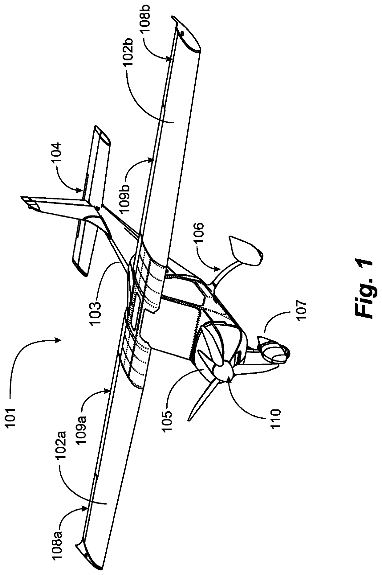
[0026]FIG. 1 is a perspective illustration of a STOL fixed-wing aircraft 101 in an embodiment of the present invention. In this example the aircraft is a fixed wing aircraft with a single engine 105 driving a propeller 110, located at the front of the aircraft. Aircraft 101 has a fuselage 103 a tail section 104 including a rudder, two fixed wings 102a and 102b landing gear 106 including a nose wheel 107, aileron apparatus 108a and 108b, and flap apparatus 109a and 109b. Propeller 110 in some embodiments may be reversible to provide braking on landing, and may be blades adjustable for thrust, as is known in the art.

[0027]Aileron apparatus 108a and b are implemented near the outboard ends of wings 102a and 102b. The use of the ailerons is well-known in the art for generating a rolling motion for the aircraft, which may precipitate a banking turn. Aileron control is critical in takeoff and landing, particularly in landing the aircraft. Ailerons usually work in opposition: as the right ...


PUM


Abstract

A flap assembly for a fixed wing aircraft, comprising first and second flap portions, a compartments in the flap portions enclosing rechargeable batteries, motor controllers and electric motors, vertically-oriented slots in the first flap portion with propellers operable through a sidewall of the slot, such that the propeller in operation extends both over and under the top and bottom walls of the flap portion. With the flap assembly retracted in the wing the propeller is entirely enclosed in the length of the slot, and wherein the flap assembly is extended from the edge of the wing, enhancing area and curvature of the wing, increasing lift on the wing, exposing the slot, and with the slot exposed the motor is started spinning the propeller, providing increased airflow over the flap assembly, further increasing lift on the wing.

Description

BACKGROUND OF THE INVENTION1. Field of the Invention[0001]The present invention is in the technology area of fixed wing aircraft and pertains more particularly to ability of such aircraft to take off and land on short runways.2. Description of Related Art[0002]The technology of Short Take Off and Landing (STOL) for fixed wing aircraft is well known in the art, and there are numerous examples in general literature and in patent literature. The length of runway for such aircraft to take off and land varies among different designs and models of aircraft, and the technology enabling STOL also varies.[0003]STOL is typically defined as an ability of an aircraft to clear a 50-foot (15 meters) obstacle within 1,500 feet (450 meters) of commencing takeoff or in landing, to stop within 1,500 feet (450 meters) after passing over a 50-foot (15 meters) obstacle.[0004]There are various reasons for providing aircraft capable of STOL, such as reduced cost for runway building and maintenance. In mil...

Claims


Application Information

Patent Timeline
IPC IPC(8): G05D1/04B64C9/20B64C3/54B64C13/02B64C13/38B64C21/04B64D31/00B64C11/28B64C11/46B64D27/02B60L50/60B64D27/24B64C9/00
CPCG05D1/042B60L50/60B64C3/54B64C9/20B64C11/28B64C11/46B64C13/02B64C13/38B64C21/04B64D27/02B64D27/24B64D31/00B60L2200/10B64C2009/005G05D1/0808B64D2027/026B64D27/08B64C13/16Y02T10/70Y02T50/10Y02T50/60B64C3/44B64C9/38B60L2240/12B60L2220/42B60L15/2009B60L50/16Y02T10/64Y02T10/72Y02T10/7072
Inventor ERWIN, CHIP WESTBOSMA, MARINUS BERNARD
Owner ERWIN CHIP WEST
Why Eureka
Try Eureka