Axial-gap dynamo-electric machine

a dynamo-electric machine and axial gap technology, applied in the direction of shielding from electromagnetic fields, windings, magnetic circuit shapes/forms/constructions, etc., can solve the problems of electrolytic corrosion of bearings, and achieve the effect of reducing shaft voltage and improving reliability against electric corrosion of bearings

Active Publication Date: 2021-11-02
HITACHI IND EQUIP SYST CO LTD
View PDF28 Cites 6 Cited by
  • Summary
  • Abstract
  • Description
  • Claims
  • Application Information

AI Technical Summary

Benefits of technology

[0010]According to an aspect of the present invention, it is possible to obtain an effect that, in an axial-air-gap dynamo-electric machine, the shaft voltage is reduced while output and efficiency are secured. Further, it is possible to obtain an effect that the reliability against electric corrosion of the bearing is improved.

Problems solved by technology

These dynamo-electric machines have a problem that a common mode voltage generated by the inverter is electrostatically coupled between the coil and the rotor to generate a potential difference (hereinafter referred to as “shaft voltage”) between the inner and outer rings of the bearing.
This is because an excessive shaft voltage causes dielectric breakdown of the lubricating oil in the bearing, so that a current flows through the bearing to cause electrolytic corrosion of the bearing (see, for example, Patent Literature 1).

Method used


Image

  • Axial-gap dynamo-electric machine
  • Axial-gap dynamo-electric machine
  • Axial-gap dynamo-electric machine

Examples


first embodiment

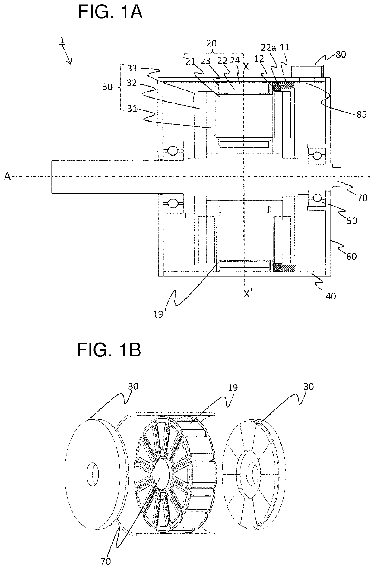
[0042]In the following, embodiments of the present invention will be described with reference to the drawings. FIG. 1(a) is a rotating-shaft direction cross-sectional view showing a configuration of an axial-air-gap motor 1 (hereinafter abbreviated as “motor 1” in some cases) of a first embodiment as an example to which the present invention is applied. Further, FIG. 1(b) is an exploded perspective view showing an overview configuration of the armature of the motor 1.

[0043]The motor 1 is a so-called double-rotor type dynamo-electric machine in which a stator 19 having a schematically circular donut shape is arranged to plane-face two disk-shaped rotors 30 so as to be sandwiched between the two rotors 30 in the shaft direction.

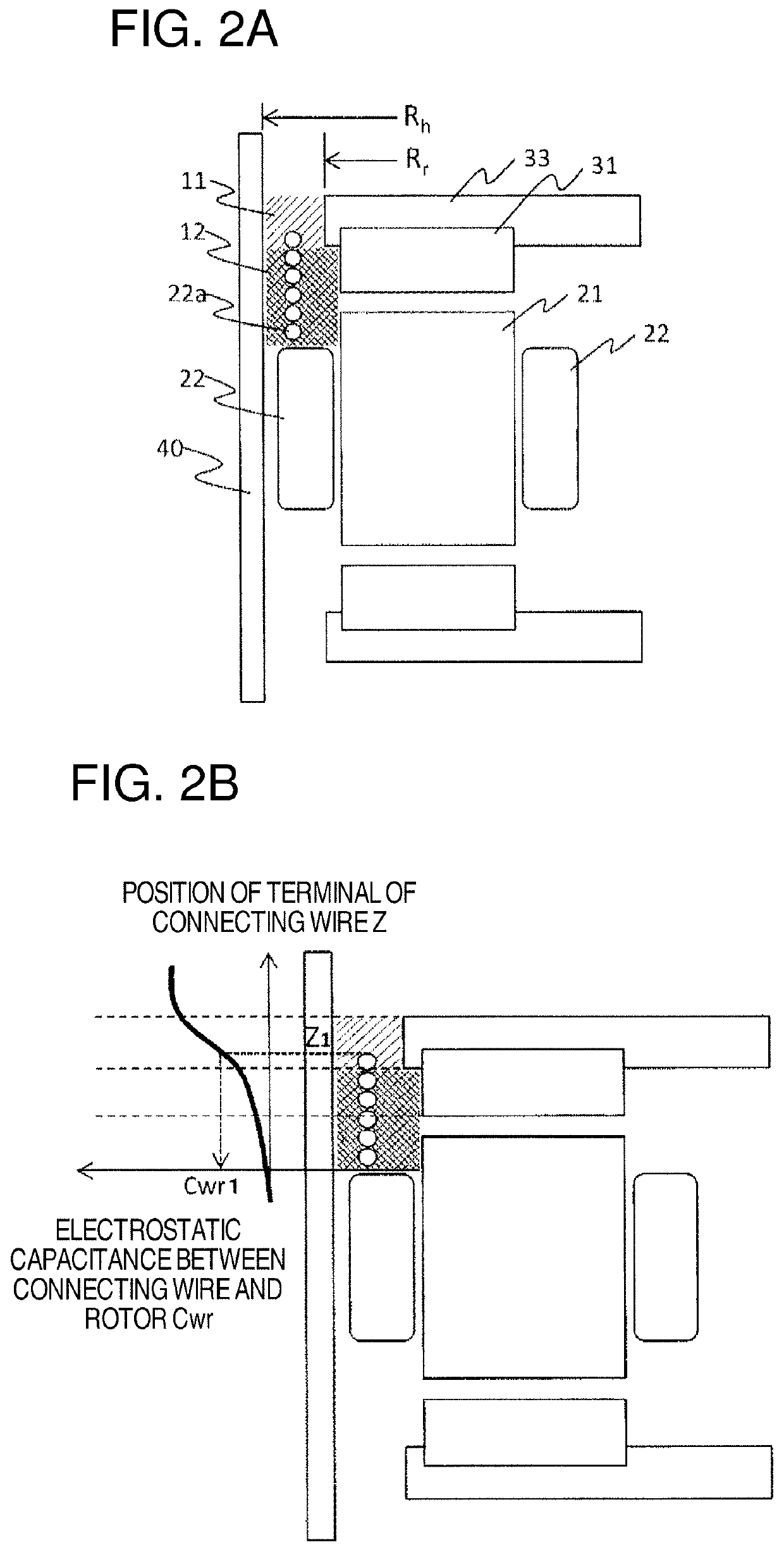
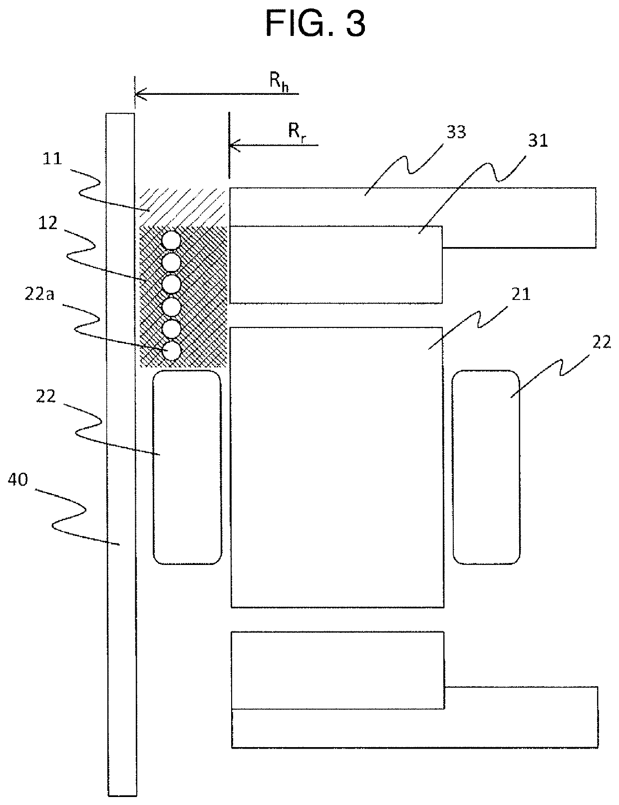
[0044]The stator 19 has a configuration in which a plurality of stator cores 20 are arranged in a circle around a shaft 70 (in the present embodiment, the stator 19 has twelve stator cores 20). The stator core 20 is configured by: a prismatic body core 21 havin...

second embodiment

[0060]One of the characteristics of the motor 1 of the second embodiment, to which the present invention is applied, is that the motor 1 is provided with two layers of the connecting wires 22a.

[0061]FIG. 4(a) is a partial cross-sectional enlarged view of the motor 1 of the second embodiment. It should be noted that the same portions as those in the first embodiment are denoted by the same reference numerals and characters and the explanation thereof is omitted.

[0062]Two layers of the connecting wires 22a are arranged close to the coil 22 in the second region 12 so that the two layers are arranged in the rotating shaft center direction. The distance between the connecting wires 22a and the first region 11 is further increased. Further, in the present embodiment, two layers of the connecting wires 22a are provided, and hence, a holding member for stabilizing the connecting wires 22a is provided.

[0063]FIG. 4(b) shows a holding member 25 which can be used for positioning the connecting...

third embodiment

[0066]One of the characteristics of the motor 1 of a third embodiment, to which the present invention is applied, is that the connecting wires 22a are arranged symmetrically on the inside surface side of the housing 40.

[0067]FIG. 5(a) is a cross-sectional view along the line X-X′ in FIG. 1. Further, FIG. 5(b) schematically shows a development view of the connecting wires 22a which are arranged centering on the line Y-Y′ in FIG. 5(a). It should be noted that the same portions as those in the first embodiment are denoted by the same reference numerals and characters and the explanation thereof is omitted.

[0068]As shown in FIG. 5(a), the connecting wires 22a led out respectively from the stator cores 20a to 20l are arranged symmetrically with respect to the line Y-Y′ obtained by connecting the terminal box 80 (hole) and the shaft of the rotor 30. As shown in FIG. 5(b), the circumferential wire portions of the connecting wires of the stator cores 20c more away from the terminal box 80 a...


PUM


Abstract

This invention reduces the shaft voltage of an axial-air-gap dynamo-electric machine while ensuring high output and high efficiency. Said axial-air-gap dynamo-electric machine comprises the following: a stator comprising a plurality of stator cores, each of which comprises a core and a coil, arranged in a circle around a shaft; a housing, the inside surface of which faces the stator radially; and at least one rotor, the surface of which faces the surface of the stator with a prescribed air gap interposed therebetween in the radial direction of the shaft. The rotor has, on the outside thereof, a conductive section comprising a conductive member. This axial-air-gap dynamo-electric machine has a first region where the inside surface of the housing faces the aforementioned conductive section radially and a second region, closer to the stator than the first region is, that extends to the coil side surfaces that face the rotor. The proportion of connecting wires in the second region is higher than in the first region.

Description

TECHNICAL FIELD[0001]The present invention relates to an axial-gap dynamo-electric machine, and more particularly to an axial-air-gap dynamo-electric machine having a stator configured by a plurality of stator cores.BACKGROUND ART[0002]For energy conservation of electric apparatuses, and the like, the use of dynamo-electric machines, such as a variable speed machine and a permanent magnet synchronous machine, driven by an inverter, has been increased. These dynamo-electric machines have a problem that a common mode voltage generated by the inverter is electrostatically coupled between the coil and the rotor to generate a potential difference (hereinafter referred to as “shaft voltage”) between the inner and outer rings of the bearing. This is because an excessive shaft voltage causes dielectric breakdown of the lubricating oil in the bearing, so that a current flows through the bearing to cause electrolytic corrosion of the bearing (see, for example, Patent Literature 1).[0003]Paten...

Claims


Application Information

Patent Timeline
Patent Type & Authority Patents(United States)
IPC IPC(8): H02K11/01H02K3/52H02K11/40H02K1/20H02K9/08H02K21/24H02K5/22
CPCH02K11/0141H02K1/20H02K3/524H02K9/08H02K11/40H02K5/225H02K21/24
Inventor TOKOI, HIROOKITAKAHASHI, SHUUICHIYONEOKA, YASUEISUZUKI, TOSHIFUMISAKAI, TORUYAMAZAKI, KATSUYUKIIWASAKI, NORIHISAMASAKI, RYOUSOUENOMOTO, YUJI
Owner HITACHI IND EQUIP SYST CO LTD
Why Eureka
Try Eureka