
Guide vane for a turbomachine

a technology of turbomachines and guide vanes, which is applied in the direction of machine/engine, leakage prevention, engine seals, etc., can solve problems such as damage to turbine blades, and achieve the effect of significantly simplifying casting and machining of the platform

Active Publication Date: 2021-11-16
SIEMENS ENERGY GLOBAL GMBH & CO KG
View PDF21 Cites 0 Cited by
  • Summary
  • Abstract
  • Description
  • Claims
  • Application Information

AI Technical Summary

Benefits of technology

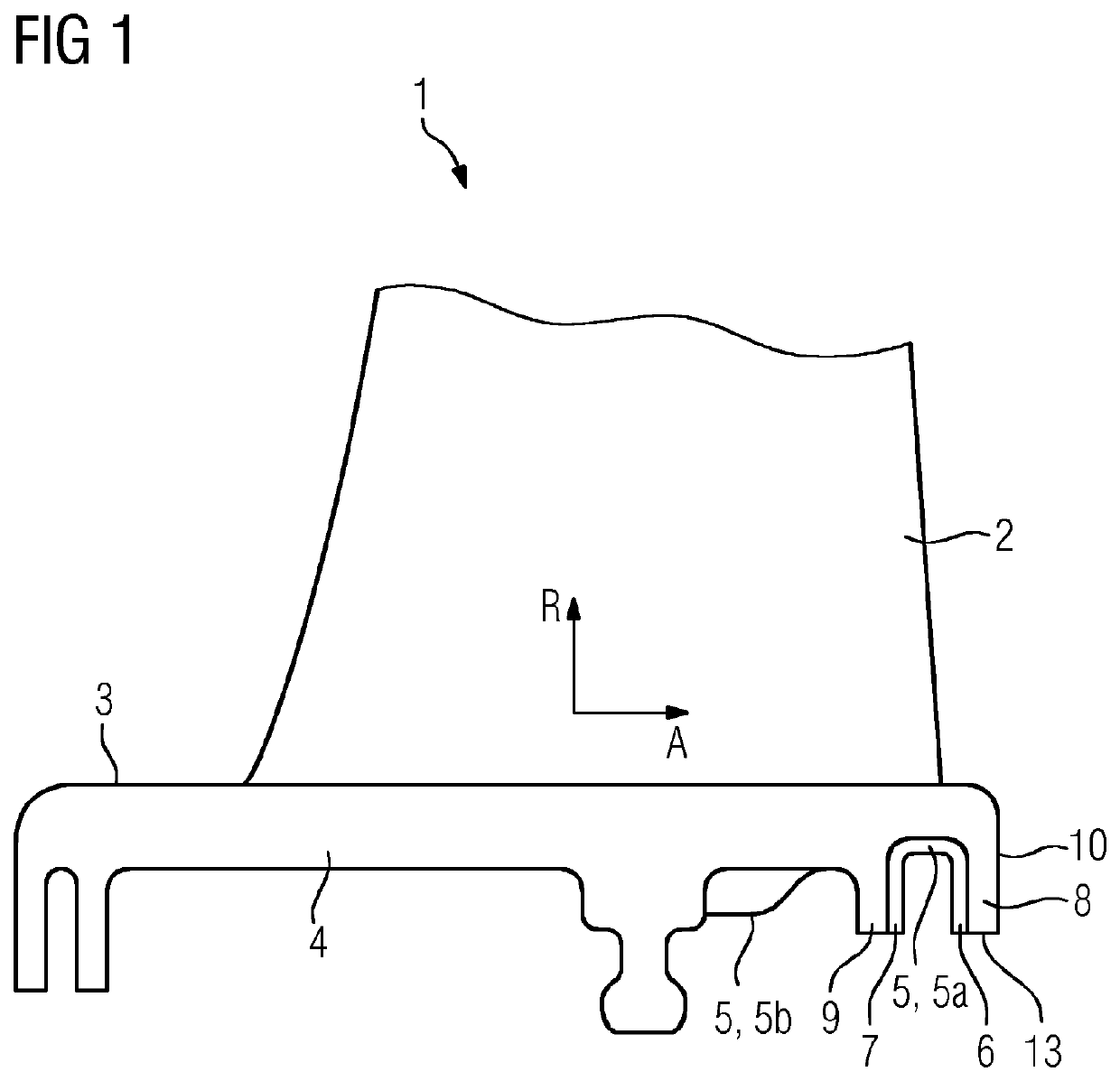
The present invention provides a guide vane with a cooling system that is effective and uniform in cooling the entire platform, which prevents thermal stresses and damage to the guide vane. The guide vane is assembled from a platform base part and at least one platform attachment part which contains at least one cooling duct. The cooling duct and other parts of the cooling system are at least in part defined by the platform attachment part. The platform can be easily cooled with small cooling ducts, and the casting and machining of the platform are simplified with the multiple-part configuration. The platform can also be jammed between the seal lips or the seal lip and the leg of the termination plate for added strength. The platform base part and / or the platform attachment part can be produced from a nickel-based super alloy, which has good resistance to temperature and stability in terms of oxidation and temperature.

Problems solved by technology

Damage to the turbine blades can result on account thereof.

Method used


Image

  • Guide vane for a turbomachine
  • Guide vane for a turbomachine
  • Guide vane for a turbomachine

Examples


first embodiment

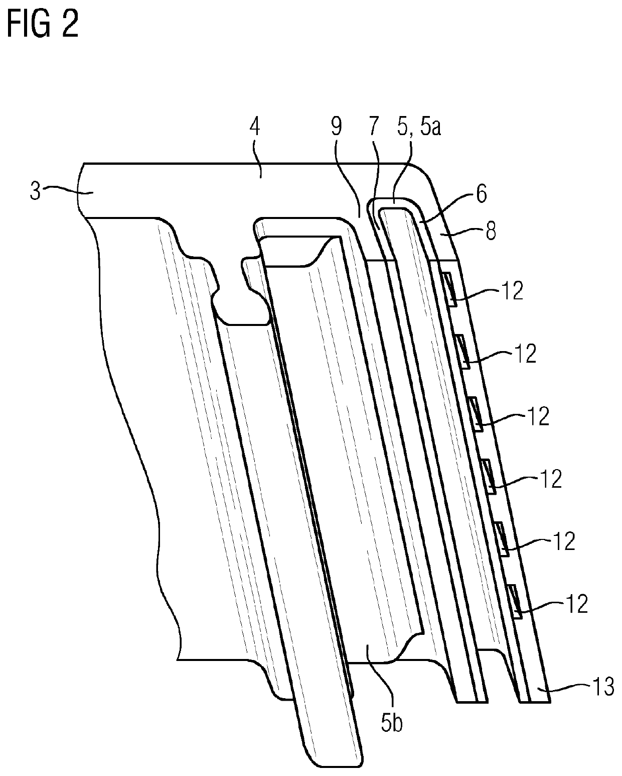
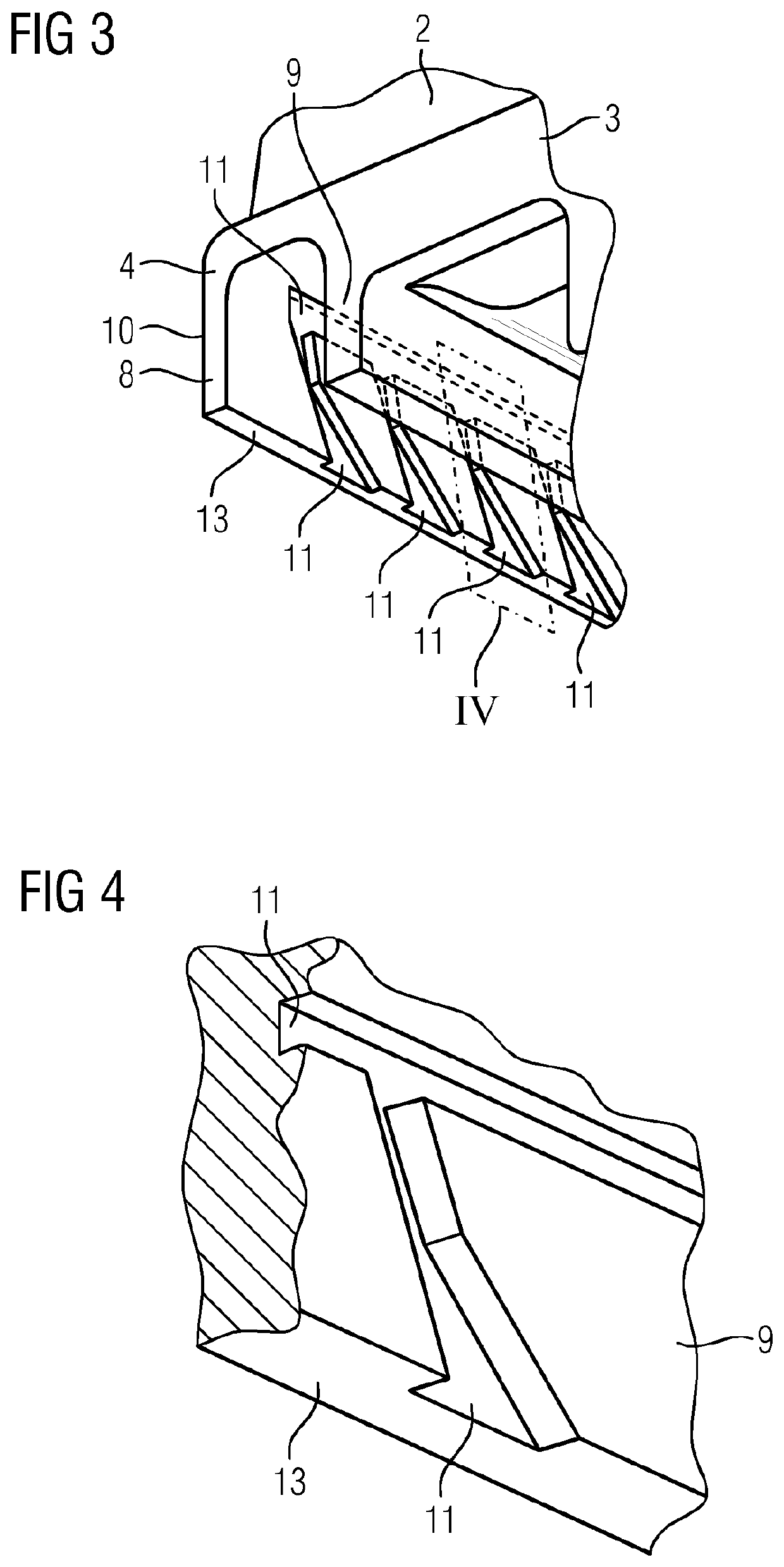
[0031]FIGS. 1 to 5 show schematic views of a guide vane 1 for a turbomachine according to the present invention. The guide vane 1 herein comprises a vane blade 2 and a platform 3 to which the vane blade 2 is connected. The platform 3 is assembled from a platform base part 4 and platform attachment parts 5 in the form of a U-shaped metal profile plate 5a having two opposite legs 6, 7, and in the form of a termination plate 5b, said plates being connected to the platform base part 4 by means of welding. The platform base part 4, for sealing in relation to a rotating system of the turbomachine, at the peripheral region thereof that is rearward in the axial flow direction A comprises two directly adjacent seal lips 8, 9 that extend so as to be mutually parallel and spaced apart and radially project from that side of the platform 3 that faces away from the blade. The seal lips 8, 9 are thus radially inward pointing sealing partners of the seal assembly which as communicating sealing part...

third embodiment

[0041]In the case of the third embodiment, the connecting ducts 15, that extend in the axial flow direction A and have likewise already been mentioned in the context of the two preceding embodiments, are cast in the platform base part 4 and, like the collection duct 16, are partially defined by the platform attachment part 5.

[0042]As can be seen in FIG. 8, the platform attachment part 5 is welded to the platform base part 4 in such a manner that the ducts 12, 14 of the platform attachment part 5 are fluidically connected to the further ducts 15, 16.

[0043]The fourth embodiment of a guide vane 1 according to the invention, shown in FIG. 8, corresponds substantially to the third embodiment. The single point of differentiation lies in that the connecting ducts 15 that extend in the axial flow direction A in the case of the fourth embodiment are bored into the platform base part 4 and are therefore completely defined by the platform base part 4.


PUM

PropertyMeasurementUnit
thermal stressesaaaaaaaaaa
temperatureaaaaaaaaaa
temperaturesaaaaaaaaaa

Abstract

A guide vane for a turbomachine, having a blade airfoil and at least one platform, to which the blade airfoil is connected. A cooling channel system is provided for cooling the platform and the blade airfoil. The platform has, on the side thereof facing the airfoil, at least one sealing lip for sealing to a rotating system of the turbomachine. At least one cooling channel extends through the sealing lip, which cooling channel forms part of the cooling channel system.

Description

CROSS REFERENCE TO RELATED APPLICATIONS[0001]This application is the US National Stage of International Application No. PCT / EP2018 / 052879 filed Feb. 6, 2018, and claims the benefit thereof. The International Application claims the benefit of European Application No. EP17155609 filed Feb. 10, 2017. All of the applications are incorporated by reference herein in their entirety.FIELD OF INVENTION[0002]The present invention relates to a guide vane for a turbomachine, having a vane blade and at least one platform to which the vane blade is connected, wherein a cooling duct system for cooling the platform and the vane blade is provided, and wherein the platform, for sealing in relation to a rotating system of the turbomachine, on the side thereof that faces away from the blade comprises at least one seal lip that projects from the platform.BACKGROUND OF INVENTION[0003]Turbine blades are used in turbomachines such as gas turbines, for instance. In principle, a differentiation is made betwe...

Claims


Application Information

Patent Timeline
Patent Type & Authority Patents(United States)
IPC IPC(8): F01D11/00F01D25/12
CPCF01D25/12F01D11/001F05D2230/21F05D2230/232F05D2230/237F05D2230/238F05D2240/12F05D2240/127F05D2300/175F01D11/025F16J15/447F05D2240/126
Inventor BEECK, ALEXANDER RALPHBOLMS, HANS-THOMAS
Owner SIEMENS ENERGY GLOBAL GMBH & CO KG
Learn More