Method for determining deformation

a deformation and measurement method technology, applied in the field of determining deformation, can solve the problems of overlay penalty, substrate deformation, mark asymmetries, etc., and achieve the effects of improving metrology, improving alignment, and improving correction of lithographic processes

Active Publication Date: 2021-11-23
ASML NETHERLANDS BV
View PDF19 Cites 0 Cited by
  • Summary
  • Abstract
  • Description
  • Claims
  • Application Information

AI Technical Summary

Benefits of technology

[0023]The inventors have devised a way to determine accurately whether process fingerprint variations originate from mark deformations or substrate deformations. It may be used for improving alignment, improving metrology and improved correction of a lithographic process, while avoiding or at least mitigating one or more of the associated problems mentioned above.

Problems solved by technology

The accurate placement of patterns on the substrate is a chief challenge for reducing the size of circuit components and other products that may be produced by lithography.
Not all distortions are correctable during exposure, however, and it remains important to trace and eliminate as many causes of such distortions as possible.
Due to processing, alignment marks and overlay targets are deformed, which results in measurement errors, causing an overlay penalty.
These processes may cause substrate deformations and mark deformations including mark asymmetries.
Typically, these bulk modifying tools may introduce mechanical stresses in the substrate resulting to strain, i.e. a deformation of the substrate.
It has been observed that the first type of equipment typically results in deformations of the alignment marks themselves, for example introducing mark asymmetries.
The second type of equipment has been observed to result in actual deformations of the substrate as a whole, thus resulting in actual displacements of the alignment marks with respect to their expected or nominal position.
However, a problem was acknowledged in WO2017009166, that it may not be possible to obtain an accurate separation of the mark deformation functions.
In the case that the column of the mixing matrix that is associated with the substrate deformation function is dependent on the other columns, it is not possible to separate the substrate deformation from the mark deformation.
However, the problem remains that there is not a clear separation between mark deformation and wafer deformation.
Consequently, it is not possible to accurately determine whether fingerprint variations originate from mark deformations or substrate deformations.
Wafer-to-wafer variations of wafer deformation fingerprints are however not determined optimally by the color separation and weighting and APC approaches discussed above, in part because they only use color separation associated with mark deformation.
Furthermore, PCA is not capable of arriving at the correct separations because of wrong intrinsic assumptions in the design of PCA, that do not map well on to the physics of deformation.
However, physical processes with a different origin (like those causing wafer and mark deformation) are mostly not orthogonal.

Method used


Image

  • Method for determining deformation
  • Method for determining deformation
  • Method for determining deformation

Examples


Embodiment Construction

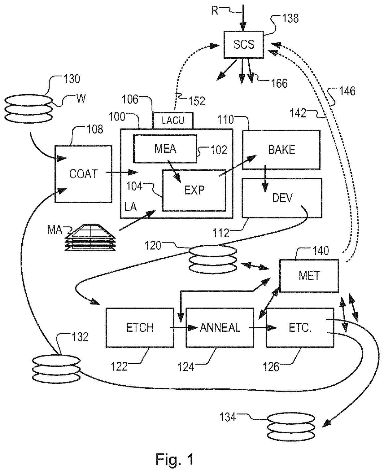
[0042]Before describing embodiments of the invention in detail, it is instructive to present an example environment in which embodiments of the present invention may be implemented.

[0043]FIG. 1 at 100 shows a lithographic apparatus LA as part of an industrial facility implementing a high-volume, lithographic manufacturing process. In the present example, the manufacturing process is adapted for the manufacture of for semiconductor products (integrated circuits) on substrates such as semiconductor wafers. The skilled person will appreciate that a wide variety of products can be manufactured by processing different types of substrates in variants of this process. The production of semiconductor products is used purely as an example which has great commercial significance today.

[0044]Within the lithographic apparatus (or “litho tool”100 for short), a measurement station MEA is shown at 102 and an exposure station EXP is shown at 104. A control unit LACU is shown at 106. In this example...


PUM

PropertyMeasurementUnit
optical metrologyaaaaaaaaaa
colorsaaaaaaaaaa
sizeaaaaaaaaaa

Abstract

A method for determining substrate deformation includes obtaining first measurement data associated with mark positions, from measurements of a plurality of substrates; obtaining second measurement data associated with mark positions, from measurements of the plurality of substrates; determining a mapping between the first measurement data and the second measurement data; and decomposing the mapping, by calculating an eigenvalue decomposition for the mapping, to separately determine a first deformation (e.g. mark deformation) that scales differently from a second deformation (e.g. substrate deformation) in the mapping between the data. The steps of determining a mapping and decomposing the mapping may be performed together using non-linear optimization.

Description

CROSS-REFERENCE TO RELATED APPLICATIONS[0001]This application is the U.S. national phase entry of PCT Patent Application No. PCT / EP2018 / 063933, filed on May 28, 2018, which claims the benefit of priority of European Patent Application No. 17177800.4, which was filed on Jun. 26, 2017 and which is incorporated herein in its entirety by reference.BACKGROUNDField of the Invention[0002]The present invention relates to a method for determining deformation, such as alignment mark deformation and substrate deformation in a lithographic process. The present invention also relates to associated methods of alignment, metrology and correcting a lithographic process, and to computer programs, computer program products, and computer apparatus.Background Art[0003]A lithographic apparatus is a machine that applies a desired pattern onto a substrate, usually onto a target portion of the substrate. A lithographic apparatus can be used, for example, in the manufacture of integrated circuits (ICs). In ...

Claims


Application Information

Patent Timeline
Patent Type & Authority Patents(United States)
IPC IPC(8): G03F9/00G03F7/20
CPCG03F9/7088G03F7/70633G03F9/7046G03F9/7076G03F9/7092
Inventor HULSEBOS, EDO MARIATINNEMANS, PATRICIUS ALOYSIUS JACOBUSBIJNEN, FRANCISCUS GODEFRIDUS CASPER
Owner ASML NETHERLANDS BV
Why Eureka
Try Eureka