
Rotary electric machine

a rotary electric machine and electric motor technology, applied in the direction of dynamo-electric machines, magnetic circuit rotating parts, magnetic circuit shapes/forms/construction, etc., can solve the problems of inefficient cooling of coils, inability to easily disperse refrigerant to stator coils, etc., to achieve efficient cooling of coils, improve the rotation efficiency of rotary electric machines, and facilitate ejection outward

Active Publication Date: 2021-12-21
HONDA MOTOR CO LTD
View PDF7 Cites 0 Cited by
  • Summary
  • Abstract
  • Description
  • Claims
  • Application Information

AI Technical Summary

Benefits of technology

The present invention provides a rotary electric machine with improved rotation efficiency and efficient cooling of the coil. The invention includes an end surface plate with a refrigerant passage groove that allows refrigerant to flow through the groove without spreading out due to surface tension. The refrigerant flows through the groove at a faster velocity, making it easier to be ejected outward by a centrifugal force. The refrigerant is also more likely to be dispersed to the coil, improving the rotation efficiency of the machine. Additionally, the invention includes a depth adjustment for the refrigerant passage groove to balance the weight of the end surface plate.

Problems solved by technology

However, if the wall body is provided on the inner circumferential surface side of the stator with respect to the refrigerant outflow opening, since a refrigerant flowing out from the outflow opening is blocked by the wall body, the refrigerant cannot be easily dispersed to the coil of the stator, and thus there is a likelihood of the coil not being cooled efficiently.

Method used


Image

  • Rotary electric machine
  • Rotary electric machine
  • Rotary electric machine

Examples


first embodiment

Rotary Electric Machine

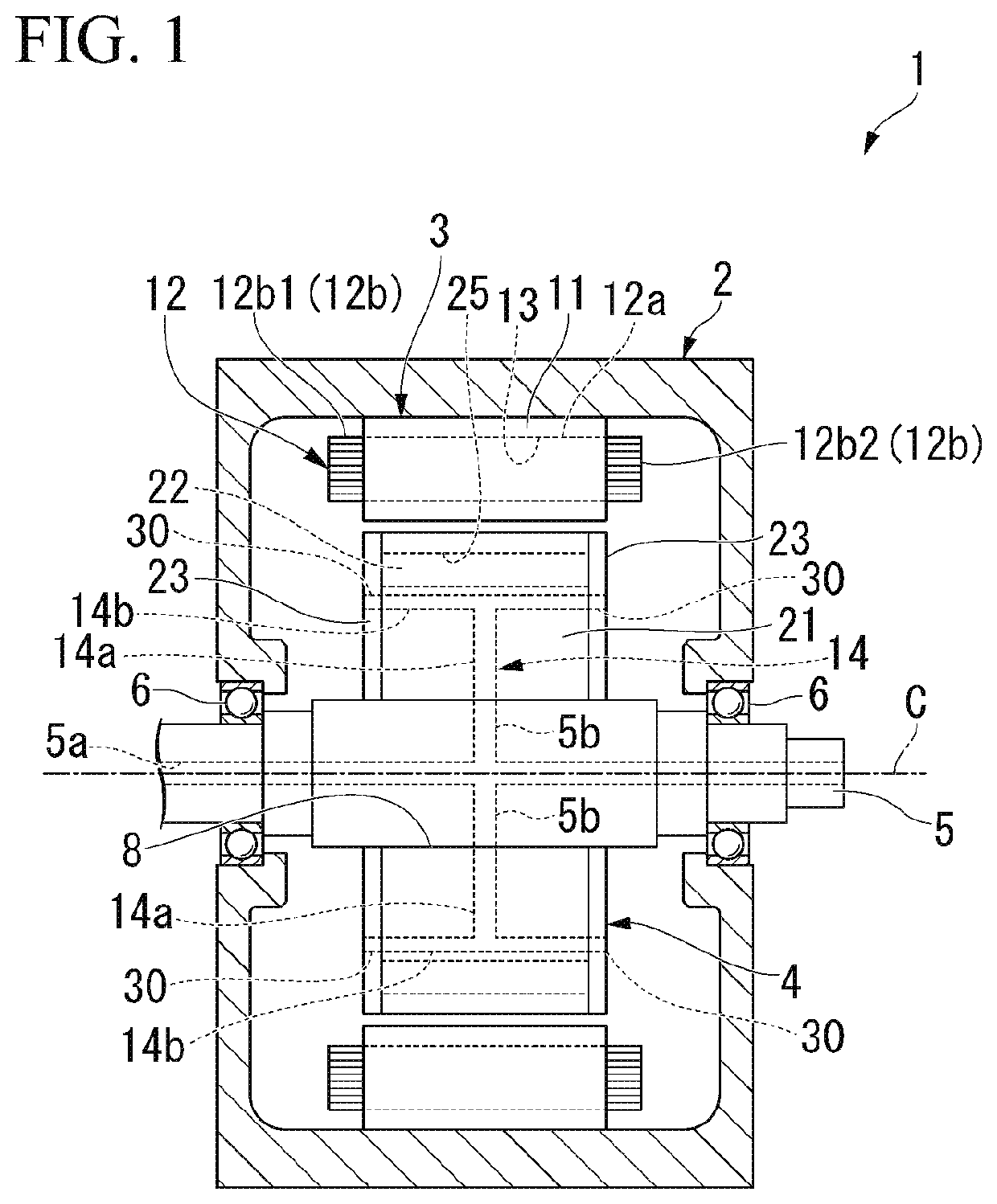
[0027]FIG. 1 is a schematic configuration view showing an overall configuration of a rotary electric machine 1 according to a first embodiment. FIG. 1 is a view including a cross section taken along a virtual plane including an axis C.

[0028]As shown inFIG. 1, the rotary electric machine 1 includes a case 2, a stator 3, a rotor 4, an output shaft 5, and a refrigerant supply mechanism (not shown).

[0029]The case 2 has a cylindrical box shape that houses the stator 3 and the rotor 4. A refrigerant (not shown) is accommodated in the case 2. A portion of the stator 3 is disposed in a state of being immersed in the refrigerant in the case 2. For example, as the refrigerant, an automatic transmission fluid (ATF), which is a hydraulic oil used for transmission lubrication, power transmission, or the like, or the like may be used.

[0030]The output shaft 5 is rotatably supported by the case 2. Reference 6 in FIG. 1 indicates a bearing that rotatably supports the output sh...

second embodiment

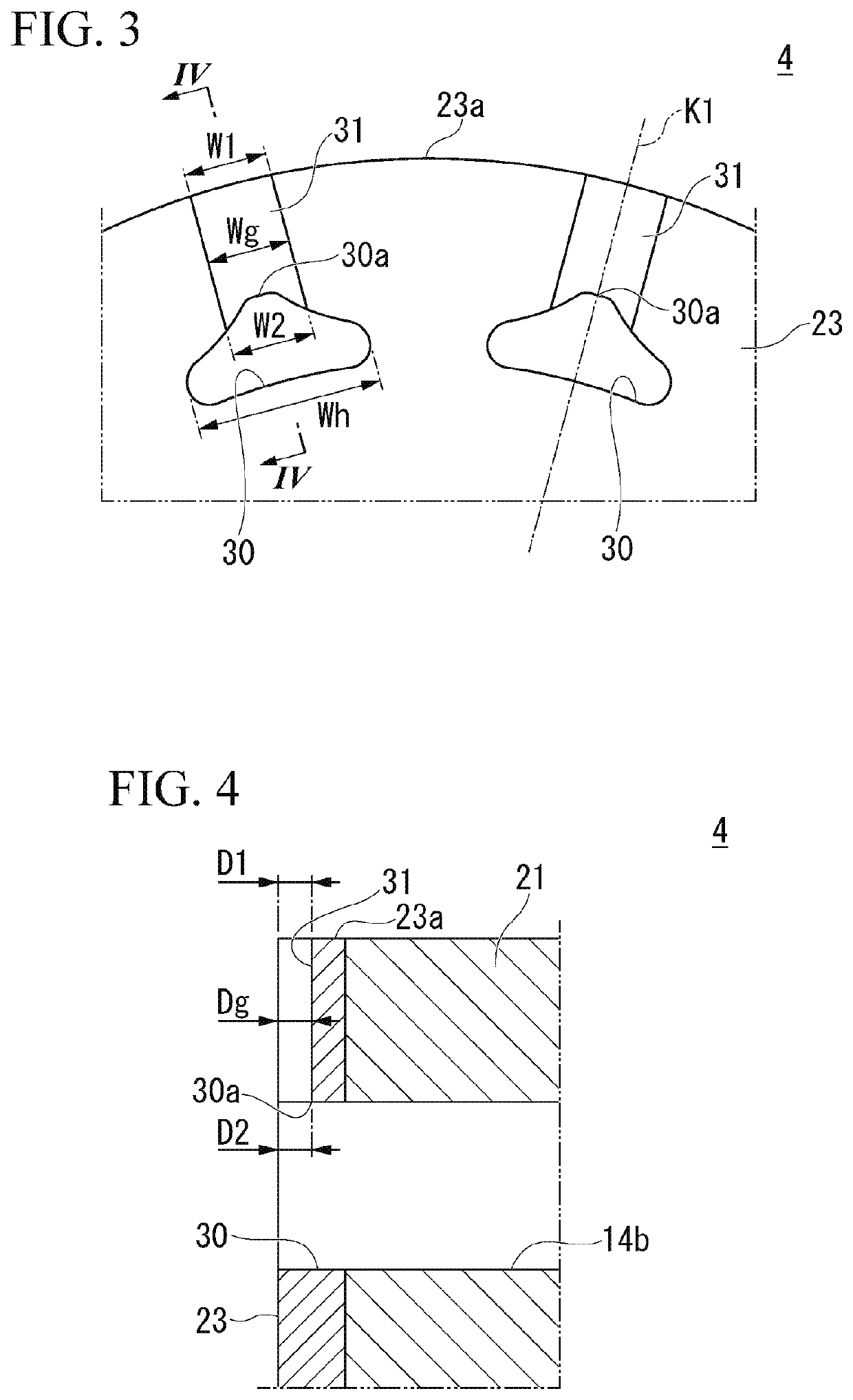
[0077]In first embodiment, description has been made by taking an example in which the radially outer groove width W1 is substantially the same as the radially inner groove width W2 in the refrigerant passage groove 31, but the present invention is not limited thereto.

[0078]FIG. 7 is a perspective view of a rotor 204 according to a second embodiment. FIG. 7 corresponds to FIG. 2 of the first embodiment.

[0079]FIG. 8 is an enlarged view showing a main portion of the rotor 204 according to the second embodiment when viewed from the axial direction. FIG. 8 corresponds to FIG. 3 of the first embodiment.

[0080]In the second embodiment, constituents the same as those in the first embodiment will be denoted by the same references, and a detailed description thereof will be omitted.

[0081]As shown in FIG. 8, a radially outer groove width W1 in a refrigerant passage groove 231 may be smaller than a radially inner groove width W2 in the refrigerant passage groove 231. When viewed from the axial ...


PUM


Abstract

A rotary electric machine of the embodiment includes a stator having a cylindrical stator core and a coil attached to the stator core, and a rotor disposed on a radially inward side of the stator, in which the rotor includes a rotor core having a rotor internal flow path through which a refrigerant can flow by axial cooling, and an end surface plate disposed at an end portion in an axial direction of the rotor core, the end surface plate includes a refrigerant flow hole which communicates with the rotor internal flow path, and a refrigerant passage groove which connects together the refrigerant flow hole and an outer circumferential edge of the end surface plate, and a radially outer groove width is equal to or smaller than a radially inner groove width in the refrigerant passage groove when viewed from the axial direction.

Description

CROSS-REFERENCE TO RELATED APPLICATION[0001]Priority is claimed on Japanese Patent Application No. 2019-003256, filed Jan. 11, 2019, the content of which is incorporated herein by reference.BACKGROUNDField of the Invention[0002]The present invention relates to a rotary electric machine.Description of Related Art[0003]In a rotary electric machine mounted on a hybrid automobile, an electric automobile, or the like, a magnetic field is formed in a stator core when a current is supplied to a coil, and thereby a magnetic attractive force or a repulsive force is generated between a magnet of a rotor and the stator core. Thereby, the rotor rotates with respect to the stator.[0004]Since a rotary electric machine generates heat according to its operation, the rotary electric machine is cooled by a refrigerant. For example, a refrigerant flow path is provided inside the rotor from a radially inward side toward a radially outward side. For example, a refrigerant once accumulated in an inner ci...

Claims


Application Information

Patent Timeline
Patent Type & Authority Patents(United States)
IPC IPC(8): H02K9/19
CPCH02K9/19H02K5/20H02K1/32
Inventor YAMAGUCHI, TADASHIKAMADA, TAKURO
Owner HONDA MOTOR CO LTD
Learn More