Process for the multistage production of methanol

a multi-stage production and methanol technology, applied in the field of methanol multi-stage production, can solve the problems of premature deactivation of the employed catalyst, complicated logistics of plant operation, and higher maximum temperatures in the catalyst bed, so as to improve the temperature control and uniform space velocity of the catalys

Active Publication Date: 2022-02-15
LAIR LIQUIDE SA POUR LETUDE & LEXPLOITATION DES PROCEDES GEORGES CLAUDE
View PDF12 Cites 3 Cited by
  • Summary
  • Abstract
  • Description
  • Claims
  • Application Information

AI Technical Summary

Benefits of technology

[0009]It is accordingly an object of the present invention to specify a process and plant which does not exhibit the described disadvantages of the prior art and which especially makes it possible in a multistage process / a multistage plant for methanol synthesis having a plurality of serially connected synthesis reactors to achieve a more uniform space velocity of the catalysts arranged in the individual reactors and further to achieve improved temperature control therein.

Problems solved by technology

However, the disadvantage of this process is that catalysts of different activity must be provided, thus complicating the logistics required for plant operation.
Excessive local temperatures, so-called “hotspots”, are a substantial factor for premature deactivation of the employed catalysts.
This results in higher maximum temperatures in the catalyst bed and an initially higher production rate which, however, then falls relatively rapidly compared to downstream reactors.
In any case, even replacement of the catalyst in only one synthesis reactor requires shutdown of the entire synthesis plant.
It is therefore unattractive to replace the catalyst in only one synthesis reactor since otherwise further shutdowns for replacement of the initially less deactivated catalysts in subsequent reactors must be expected.

Method used


Image

  • Process for the multistage production of methanol
  • Process for the multistage production of methanol

Examples


first embodiment

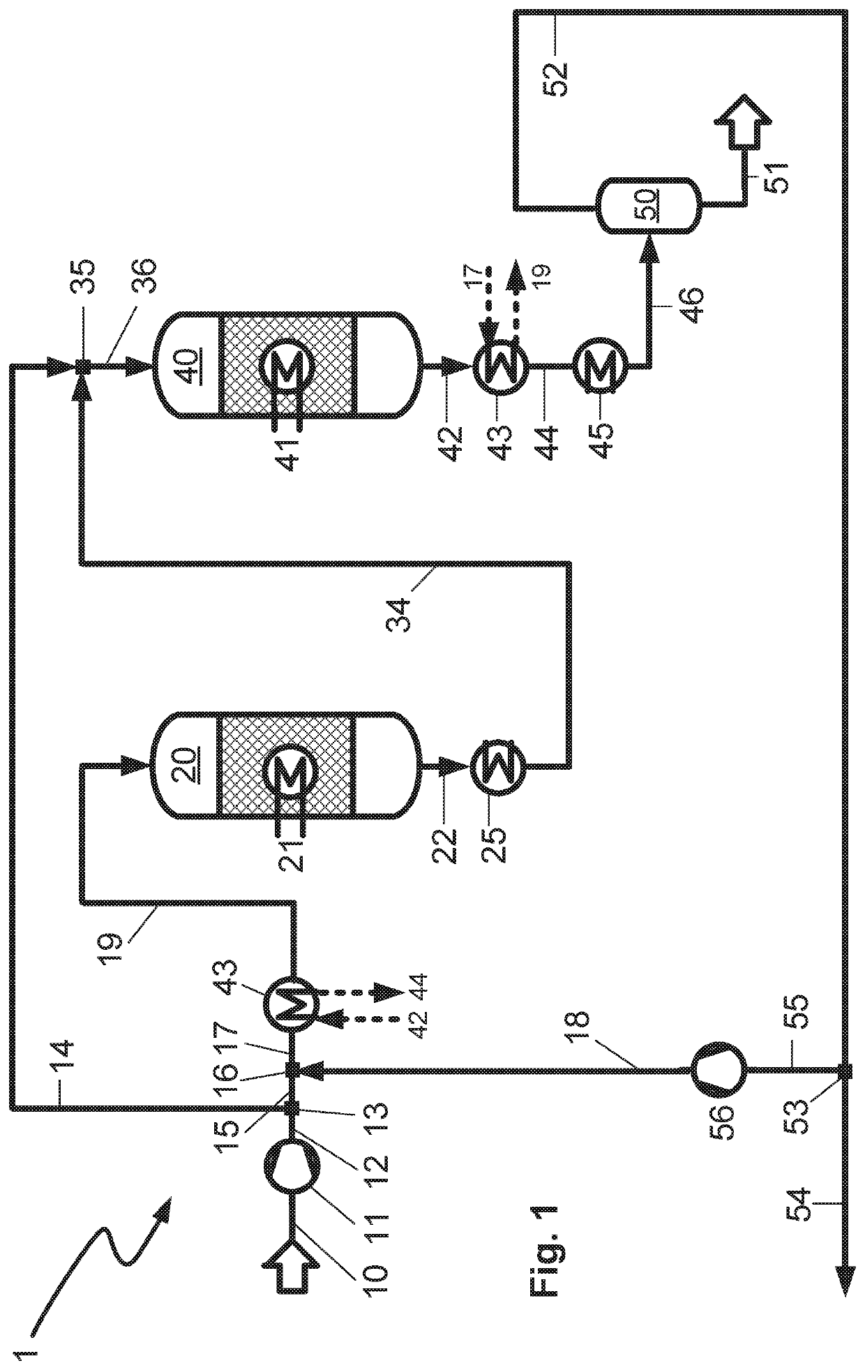
[0055]FIG. 1 is a schematic representation of the process / the plant according to the invention comprising two water-cooled reactors,

second embodiment

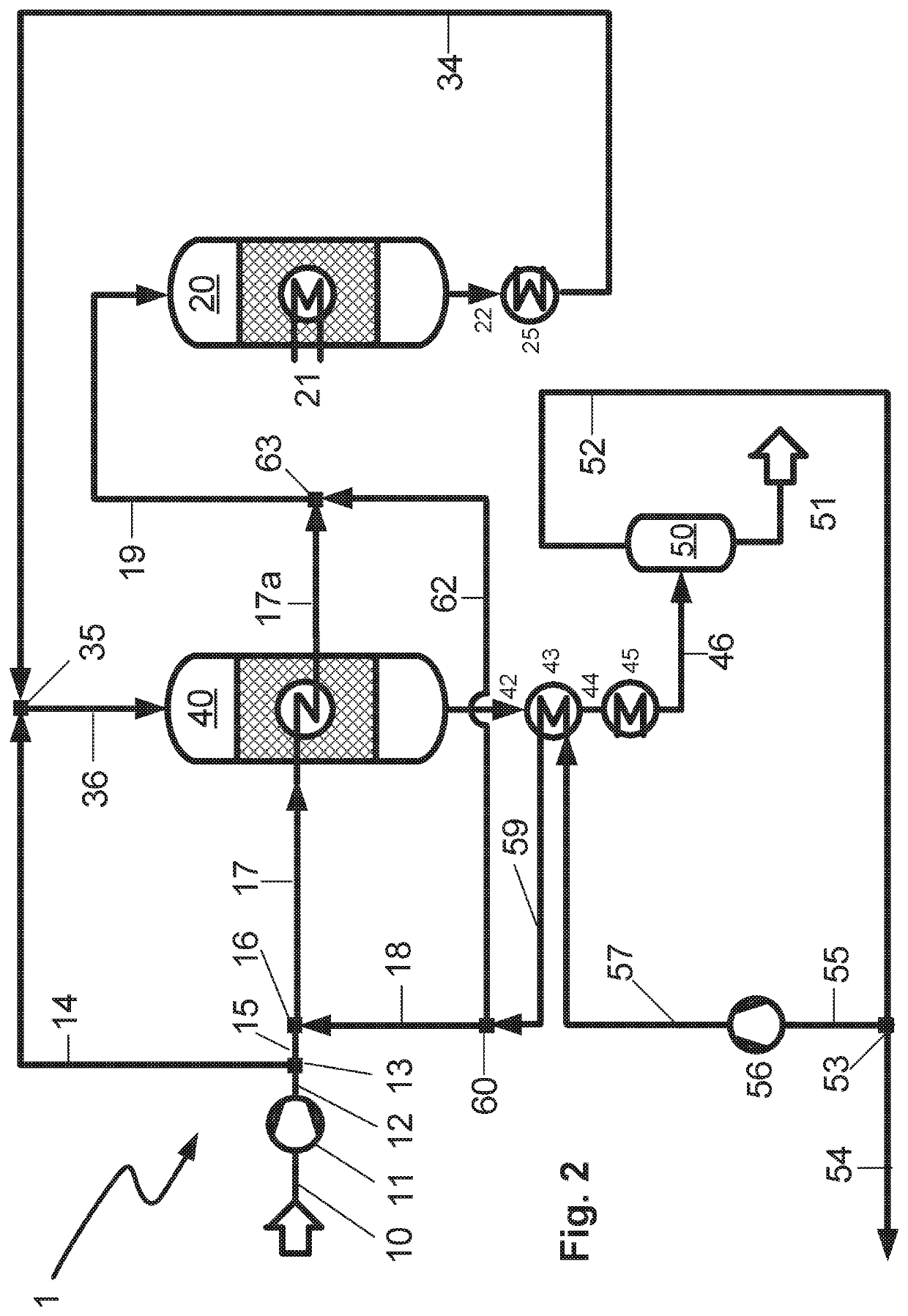
[0056]FIG. 2 is a schematic representation of the process / the plant according to the invention comprising a water-cooled reactor as the first reactor and a gas-cooled reactor as the second reactor.

DETAILED DESCRIPTION OF PREFERRED EMBODIMENTS

[0057]In the first embodiment of a process 1 / a plant 1 according to the invention shown in FIG. 1 which comprises two serially arranged, water-cooled synthesis reactors 20, 40, fresh synthesis gas (fresh gas, make-up gas) containing hydrogen, carbon monoxide and carbon dioxide from a synthesis gas production plant (not shown) is introduced via conduit 10, compressed to synthesis pressure using compressor 11 and passed via conduit 12 to a separation apparatus 13 which may be in the form of a pipe T-piece for example. A substream of the fresh gas is discharged from the separation apparatus via conduit 14 and passed as fresh gas bypass stream to the second synthesis reactor 40. A metering apparatus (not shown) may be arranged along the course of co...


PUM

PropertyMeasurementUnit
temperatureaaaaaaaaaa
diametersaaaaaaaaaa
dew pointaaaaaaaaaa

Abstract

Proposed is a process for producing methanol from synthesis gas by means of multi-stage, for example 2-stage, heterogeneously catalyzed methanol synthesis, wherein the product stream of a synthesis stage is applied to the downstream synthesis stage as a feed stream or after removal of a purge stream recycled to the first synthesis stage as a recycle stream. According to the invention a substream is removed from the synthesis gas fresh gas and introduced into the second methanol synthesis reactor as a bypass stream.

Description

CROSS REFERENCE TO RELATED APPLICATIONS[0001]This application claims the benefit of priority under 35 U.S.C. § 119 (a) and (b) to European Patent Application No. 19020578.1, filed Oct. 16, 2019, the entire contents of which are incorporated herein by reference.BACKGROUNDField of the Invention[0002]The invention relates to a process for producing methanol by heterogeneously catalyzed conversion of synthesis gas comprising hydrogen and carbon oxides over solid, granular catalysts for methanol synthesis arranged in a plurality of serially arranged fixed-bed reactors. The invention further relates to a plant for performing such a production process.Prior Art[0003]Processes for industrial production of methanol by heterogeneously catalyzed conversion of synthesis gas, i.e. mixtures of hydrogen and carbon oxides, have long been known in the art. Ullmann's Encyclopedia of Industrial Chemistry, Sixth Edition, 1998 Electronic Release, chapter “Methanol”, subchapter 5.2 “Synthesis” describes ...

Claims


Application Information

Patent Timeline
Patent Type & Authority Patents(United States)
IPC IPC(8): C07C29/151B01J19/00B01J19/24B01J35/02C07C29/152C07C29/154B01J23/72C07C31/04
CPCC07C29/1516B01J19/0013B01J19/24B01J35/026C07C29/152C07C29/154B01J23/72C07C31/04C07C29/16Y02P20/52
Inventor OELMANN, TOBIASGRONEMANN, VERONIKAHOFMANN, HEIKOSCHUHMANN, TIMM
Owner LAIR LIQUIDE SA POUR LETUDE & LEXPLOITATION DES PROCEDES GEORGES CLAUDE
Why Eureka
Try Eureka