Ultrasound device contacting

a technology of ultrasound device and contact, which is applied in the field of ultrasound device, can solve the problems of poor acoustic coupling, application difficulties, and many problems, and achieve the effect of preventing overheating of ultrasound devi

Active Publication Date: 2022-02-22
KONINKLJIJKE PHILIPS NV
View PDF23 Cites 0 Cited by
  • Summary
  • Abstract
  • Description
  • Claims
  • Application Information

AI Technical Summary

Benefits of technology

[0017]The device preferably is also capable of reducing the contact pressure if it becomes too high. An actuation level may then be reduced to a desired level. The same feedback loop can be used for this. The controller can also be configured to provide this function. A biased spring opposing the actuation caused biasing can be used to aid the reduction of pressure when actuation is lessened. Some actuators may be slow in switching from high to lower level of actuation and the spring may aid to increase the switching and thus feedback speed. Even a further actuator that opposes the one for increasing the contact pressure can be used for this in combination with appropriate feedback and control by the controller. The actuators can be used as antagonists.
[0034]The acoustically transmissive window may further comprise a further elastomer layer having electrically conductive particles and optionally electrically insulating particles dispersed therein, the elastomer layer having a temperature-sensitive electrical conductivity, the ultrasound device further comprising a further electrode arrangement coupled to said further elastomer layer adapted to measure said temperature-sensitive conductivity. Such a further elastomer layer may be independently optimized to provide temperature information in addition to the pressure information provided by the elastomer layer. Such temperature information for example may be used to measure the quality of the contact between the ultrasound device and the patient's body and / or to prevent overheating of the ultrasound device.

Problems solved by technology

Such applications face several challenges.
For instance, in imaging applications it is far from trivial to achieve a good contact between the ultrasound transducer array and the part of the body to be imaged.
A very low pressure or no contact results in poor acoustic coupling.
A high contact pressure leads to discomfort, safety issues or impact / mechanical damage.
However, a drawback of this approach is that usually large amounts of gel have to be used, which may contain air bubbles that interfere with the transmission or reception of the ultrasound signals.
Moreover, the ultrasound transducer array, e.g. in the form of the probe, is typically hand-held during an imaging procedure, which makes the procedure prone to errors.
In addition, there are instances where a hand-held solution is not viable, such as for example when imaging is performed from locations inside the body.
This for example applies to large area ultrasound transducers (e.g. wearable US patches) and transesophageal echocardiogram (TEE) probes, where it is notoriously difficult to establish a good contact between the ultrasound transducers and the body region to be imaged or treated.
Manual manipulation of ultrasound probes is also difficult when imaging is done as part of monitoring over a longer periods of time such as for example longer than hours, either continuously or with multiple imaging instances distributed during the monitoring time.
Similar challenges exist in therapeutic applications, where the focused beam requires periodic readjustment to treat multiple regions of the diseased tissue.
The manual adjustment is prone to inaccuracies and the range of phase controlled beam steering may not be sufficient to reach all diseased tissue without array displacement.

Method used


Image

  • Ultrasound device contacting
  • Ultrasound device contacting
  • Ultrasound device contacting

Examples


Embodiment Construction

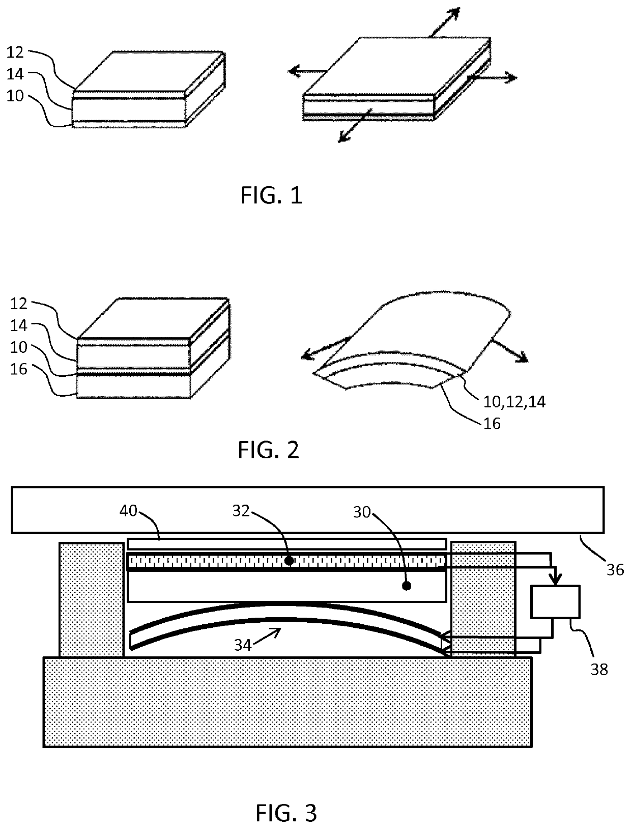
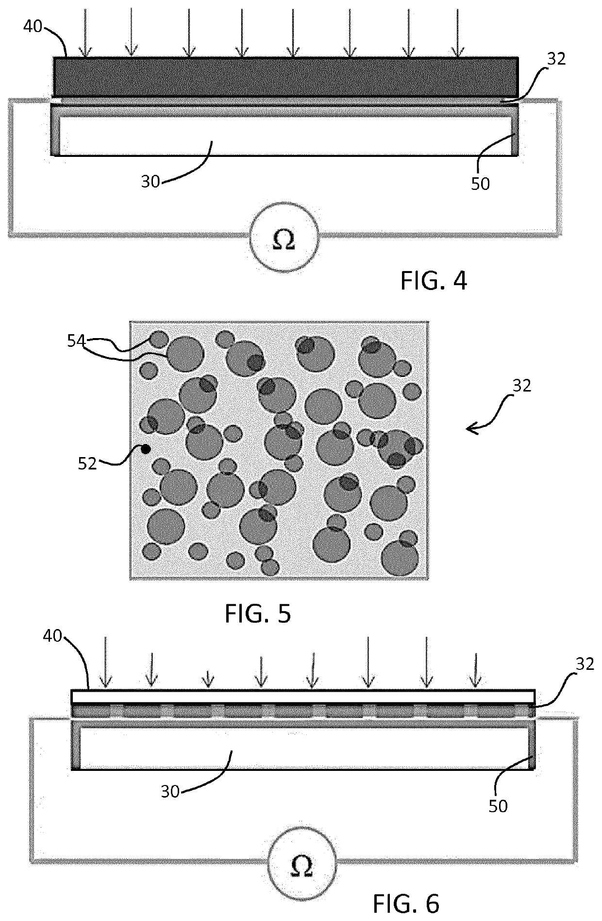
[0045]In the context of the present application, the term ‘conductive’ means ‘electrically conductive’ unless explicitly stated otherwise. Similarly, the term ‘non-conductive’ means ‘electrically insulating’ unless explicitly stated otherwise. Instead of conductivity, resistivity can be measured. This is considered equivalent as both conductivity and resistivity are parameters for indicating the extent to which a material is capable of conducting current.

[0046]The feedback signal may be in the form of a current value measured or a voltage parameter measured. Likewise a resistivity or conductivity value may be calculated from voltage and current measurements.

[0047]The invention makes use of an actuator using an electroactive material (EAM), This is a class of materials within the field of electrically responsive materials. When implemented in an actuation device, subjecting an EAM to an electrical drive signal can make them change in size and / or shape. This effect can be used for act...


PUM

PropertyMeasurementUnit
temperaturesaaaaaaaaaa
thicknessaaaaaaaaaa
thicknessaaaaaaaaaa

Abstract

An ultrasound device comprises a transducer arrangement and an acoustically transmissive window over said arrangement, said window comprising an elastomer layer having conductive particles dispersed in the elastomer, the elastomer layer having a pressure-sensitive conductivity. An electroactive material actuator is provided for biasing the transducer arrangement towards the transmissive window. The electroactive material actuator is controlled in dependence on a measured pressure-sensitive conductivity. In this way, a feedback system is provided for controlling a contact pressure. The device can be implemented with low cost and with low power consumption.

Description

CROSS-REFERENCE TO PRIOR APPLICATIONS[0001]This application is the U.S. National Phase application under 35 U.S.C. § 371 of International Application No. PCT / EP2017 / 078518, filed on Nov. 8, 2017, which claims the benefit of EP Patent Application No. EP 16198779.7, filed on Nov. 15, 2016. These applications are hereby incorporated by reference herein.FIELD OF THE INVENTION[0002]The present invention relates to an ultrasound device comprising a transducer arrangement for application to the skin.BACKGROUND OF THE INVENTION[0003]Ultrasound waves find several applications in medicine. One such application is ultrasound imaging, wherein ultrasound waves are emitted by an ultrasound device comprising an array of ultrasound transducers into the body of a patient and echoes of the ultrasound waves are collected by the ultrasound transducers or by dedicated ultrasound receivers and processed to generate an ultrasound image, e.g. a 1D, 2D or 3D ultrasound image. Another application is ultrasou...

Claims


Application Information

Patent Timeline
Patent Type & Authority Patents(United States)
IPC IPC(8): A61B8/00
CPCA61B8/54A61B8/4455A61B8/4483A61B8/429A61B8/4444A61B8/58
Inventor HAKKENS, FRANCISCUS JOHANNES GERARDUSBELT, HARM JAN WILLEMJOHNSON, MARK THOMASVAN DEN ENDE, DAAN ANTON
Owner KONINKLJIJKE PHILIPS NV
Why Eureka
Try Eureka