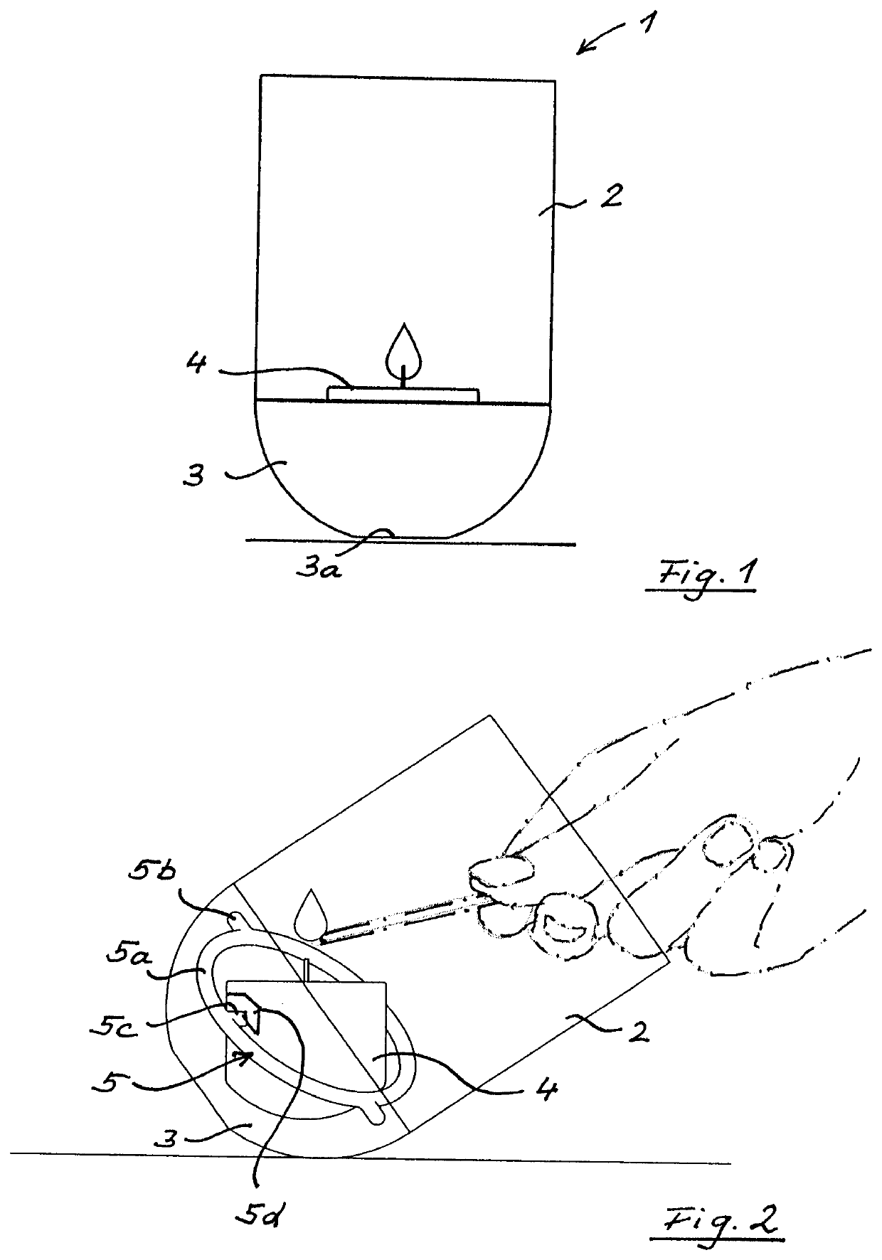
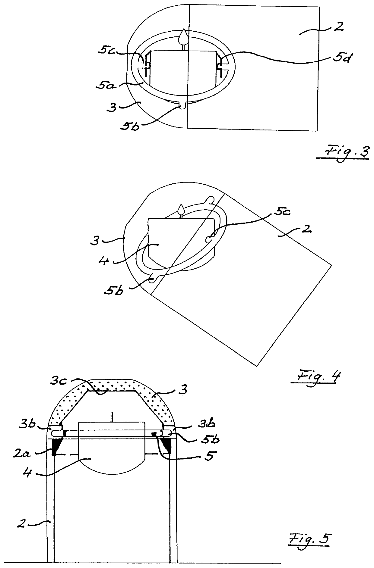
[0016]FIG. 1 shows a burning lamp 1, in particular in the form of a wind light, with a base 3 and a translucent housing part 2 placed on it, and with a support tray 4 (for a burning agent). The burning agent is preferably a wax candle whose wick is lit here, as schematically indicated by a flame. As described below, the support tray 4 is pivotable by means of a gimbal suspension 5 relative to the housing part 2 and also to the hemispherical base 3 about two axes (5b-5b; 5c-5c), each formed by two correspondingly coaxial pins. Such a construction is also useful for food containers, in which case the support tray 4 contains e.g. a sugar supply (or a variable fragrance dispenser).
[0017]As shown in FIG. 2 (and the other figures), on ring 5a, two pins 5b are directed radially outward and two pins 5c are directed radially inward towards support tray 4. Therefore, the support tray 4 can move in two dimensions, i.e. it has two so-called degrees of freedom, so that the support tray 4 always remains exactly aligned in its horizontal plane regardless of the inclination of the burning lamp 1 and thus no burning agent (e.g. oil) can leak out. The base 3 has a substantially hemispherical outer shape, so that the burning lamp 1 can simply be tilted into the lighting position shown here (and also remains stable in this position), in order to light the burning agent with a match, as shown here in dashed/dotted lines. Tilting the lamp to almost any inclination is particularly advantageous when lighting the lamp, as the wick of the burning agent is often relatively flat and the burning lamp 1 can therefore be tilted preferably in this direction in order to reach the wick easily with a match within the usually rather narrow glass tube. The good accessibility also applies to a sugar bowl, for example, where a teaspoon is used instead of a match to access the sugar supply in the support tray 4. The tray itself remains in a horizontal position in every tilting direction, so that the sugar supply is easily accessible, but in the “upside down” position (see FIG. 5) it is hygienically covered.
[0018]Although the burning lamp 1 is inherently stable in the tilted position as shown in FIG. 2 in this position, the lower end 3a of the hemispherical base 3 is preferably flattened as a standing surface to increase stability in the normal operating position as shown in FIG. 1. In FIG. 2, adjacent to pin 5c a clip-shaped holder 5d (see also FIG. 3) is indicated, which is open towards the bottom for plugging the support tray 4 onto the two inwardly directed pins 5c. In FIGS. 3 and 4 the burning lamp 1 is shown in strongly tilted positions, namely in the horizontal position (FIG. 3) and tilted by another 45°. This shows that the support tray 4 inside the Cardan ring (gimbal ring) 5a always remains in horizontal position. The Cardan ring 5a is preferably configured with the four pins 5b, 5c as a metal casting in order to achieve high stability and cost-effective production.
[0019]FIG. 5 shows the burning lamp 1 in its overhead extinguishing position. The base 3 is here cut in its central plane along its main extension, whereby a vaulted shape or cavity 3c is visible. Since the flame is still burning at the transition from FIG. 4 to FIG. 5, the base 3 or at least its cavity 3c is made of a temperature-resistant material, namely metal or ceramic, as shown dotted here. At the transition between base 3 and the housing part 2 below, two opposite slots 3b are further visible, into which the pins 5b, which project outwards, are inserted when components 2 and 3 are separated from each other. The slots 3b are aligned parallel to the main extension of the burning lamp 1 and are adjacent to an (here upper) end face of the translucent housing part 2, so that the pins 5b are mounted therein to form one of the two degrees of freedom of the gimbal suspension 5.
[0020]For easy fixation between base 3 and the translucent housing part 2, in particular a hollow glass cylinder, a connecting sleeve 2a can be inserted, which creates an annular coupling zone (shown here blackened) between the components 2 and 3. The connecting sleeve 2a can also have a thread, a bayonet lock or similar positive and/or frictional coupling elements, and can also be connected to base 3 in one piece. As known per se, the burning lamp 1 can be designed in the manner of a floor lamp or hanging lamp. What is new, however, is that the burning lamp 1 can be mounted on a rod with a simple upper recess without the need for any further attachments, due to its inherent stability as described above (see FIG. 2). Such a rod is preferably an earth spike, so that the burning lamp 1 can be positioned especially at a height of e.g. 80 cm in the garden for better illumination. The support tray 4 is filled with fuel, e.g. oil or wax, whereby fragrances can also be provided.
[0021]All in all, this results in an attractive lighting with long burning time and safe, comfortable handling of the burning lamp 1, which can of course also be used indoors as a table lamp etc. Here, too, the advantage of safe, easy extinguishing of the flame through the “overhead” rotation, with practically any tilting direction due to the Cardan bearing, can advantageously be used, as can the convenient lighting.
[0022]The same applies to the independently claimed suspension in a lower part, in particular a base and an upper housing part, wherein the gimbal suspension 5 is pivotable by 180° about its two pivot axes, so that the initially upper (in FIG. 1) housing part 2 is arranged in this pivoted position as the base at the bottom and the original lower part 3 is then arranged as a cover at the top, as shown in FIG. 5. This suspension can preferably be used for food containers, such as a sugar bowl, for a jewelry box or an ashtray. It can also be used in a gastronomic tray (to keep food warm) or in an advertising article, in particular with an emblem which is visible in one position (see FIG. 1) with the lower part (base 3) as base and covered in the pivoted position with the lower part as the cover. In this way, surprise effects can be achieved for the person looking at it.
[0023]It should be pointed out that such (gimbal) suspensions are known to be used in levelling devices, cameras and the like; there, however, the gimbal only serves to compensate for a few degrees of inclination, while the suspension claimed here, in conjunction with the lower part, support tray and upper part, performs a pivoting movement of (about) 180° in order to achieve covering of the product located in support tray 4, whether it is a candle to extinguish it or a sugar supply to protect it from flies, for example. The same applies to an ashtray (with odor barrier) or a jewelry box (visibility cover). Preferably, each of the upper and lower parts has a hemispherical outer shape, with gimbal suspension 5 inserted in the central area.