Method and a device for managing the energy of a hybrid power plant of a multi-rotor aircraft

a technology of hybrid power plant and energy management device, which is applied in the direction of pv power plant, turbine/propulsion fuel heating, efficient propulsion technology, etc., can solve the problems of difficult to overcome low energy density of electrical energy source, noise, and environmental constraints of such aircraft, so as to optimize the consumption of thermal energy and electrical energy

Active Publication Date: 2022-03-15
EUROCOPTER
View PDF27 Cites 0 Cited by
  • Summary
  • Abstract
  • Description
  • Claims
  • Application Information

AI Technical Summary

Benefits of technology

[0026]An object of the present invention is thus to provide a method of managing the energy of a hybrid power plant of a multi-rotor aircraft during a flight of the aircraft, which method makes it possible to avoid the above-mentioned limitations while optimizing the consumption both of thermal energy and of electrical energy by the hybrid power plant. Another object of the present invention is to provide an aircraft having a device for managing the energy of a hybrid power plant of a multi-rotor aircraft during a flight of the aircraft by performing the method.
[0027]The method and the device for managing energy of a hybrid power plant thus enable the consumption of energy by the multi-rotor aircraft to be optimized while satisfying the three above-mentioned essential criteria for a mission of aerially transporting one or more passengers and / or goods, namely: respecting the environment; and limiting both the weight of the multi-rotor aircraft and also the cost of operating it.
[0050]Using only electrical energy as delivered by the electrical energy source during takeoff and landing stages serves advantageously to reduce the level of sound nuisance and to eliminate the atmospheric pollution generated by the multi-rotor aircraft. Furthermore, and unlike a thermal engine, an electrical energy source and an electric motor can deliver their maximum power without needing to reach an operating temperature. Specifically, the takeoff stage may advantageously be performed quickly without waiting for a warm-up time. The takeoff procedure is thus shorter compared with an aircraft using a thermal engine for the takeoff stage, and the time saving is not negligible, given the short duration of the flight.
[0051]Furthermore, the third calculation of the available electrical cruising energy EElecCruise for the cruising stage and the comparison of the electrical cruising power WElecCruise with the cruising power WCruise serve advantageously to limit the use of the thermal energy source to the minimum needed, and thereby limit the atmospheric pollution generated by the multi-rotor aircraft to the strict minimum. In addition, the method of the invention also makes it possible to consume a maximum amount of electrical energy from the electrical energy source of the hybrid power plant.
[0052]Knowing the use that is to be made of the thermal energy source during a flight thus makes it possible to take on board just enough fuel for the needs of the thermal energy source, thereby correspondingly increasing the payload of the multi-rotor aircraft.

Problems solved by technology

Furthermore, being located in sensitive zones imposes environmental constraints on such aircraft both in terms of noise and in terms of polluting emissions.
Furthermore, each thermal engine is then a source of atmospheric pollution during such stages of takeoff and landing.
Nevertheless, the weight of an electrical power plant and the low energy density of an electrical energy source constitute obstacles that are difficult to overcome at present.
Specifically, the large weight of electrical energy storage devices limits the distance that can be traveled by such a multi-rotor aircraft and limits the payload that can be transported.

Method used


Image

  • Method and a device for managing the energy of a hybrid power plant of a multi-rotor aircraft

Examples


Embodiment Construction

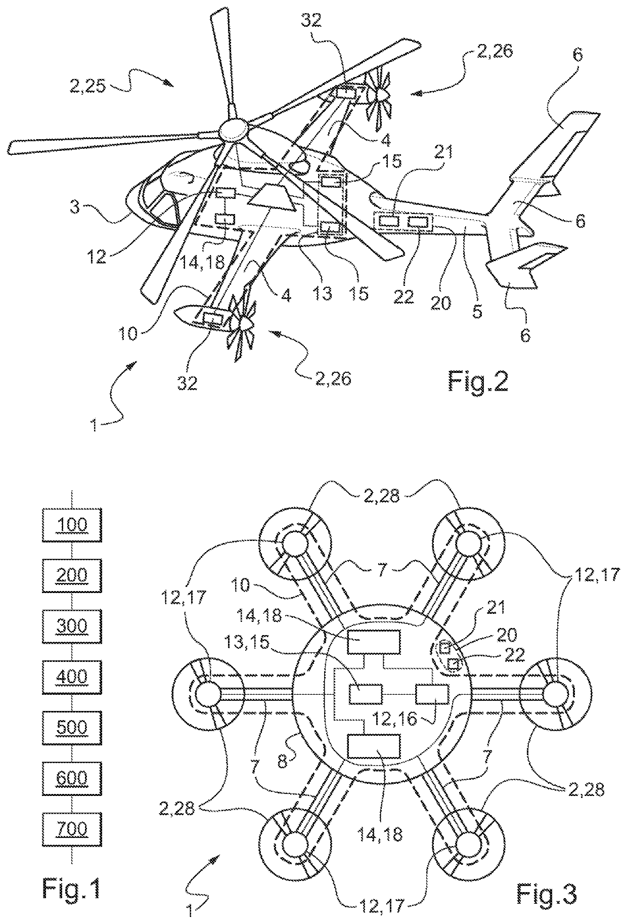
[0094]Elements present in more than one of the figures are given the same references in each of them.

[0095]FIG. 1 is a block diagram of a method of managing the energy of the hybrid power plant of a multi-rotor aircraft 1. FIGS. 2 and 3 show two examples of a multi-rotor aircraft 1 fitted with a hybrid power plant 10 and with a device 20 for managing the energy of the hybrid power plant 10 of the multi-rotor aircraft.

[0096]The method and the device 20 serve to determine, and consequently to optimize, the distribution of how different kinds of energy are consumed in the hybrid power plant 10 of the multi-rotor aircraft 1 over a complete flight.

[0097]In a manner that is common to both of these examples, a multi-rotor aircraft 1 has a hybrid power plant 10, a device 20 for managing the energy of the hybrid power plant 10, and a plurality of rotors 2 driven in rotation by the hybrid power plant 10. The hybrid power plant 10 has at least one thermal engine 15 constituting a thermal energ...


PUM


Abstract

A method and to a device for managing energy of a hybrid power plant of a multi-rotor aircraft during a flight. The hybrid power plant comprises a thermal engine, an electricity generator, and a plurality of electric motors, together with a plurality of electrical energy storage devices. The aircraft has a plurality of rotors driven in rotation by respective electric motors. The flight of the aircraft comprises a takeoff stage, a cruising stage, and a landing stage, the takeoff stage and the landing stage being performed solely while consuming electrical energy. The method enables an electrification ratio RElec of the flight to be calculated as a function of the amounts of electrical and thermal energy that are consumed during the takeoff, landing, and cruising stages, thereby limiting the use of the thermal engine to the least possible amount during the cruising stage, and consequently reducing the associated nuisance.

Description

CROSS-REFERENCE TO RELATED APPLICATIONS[0001]This application claims priority to French patent application No. FR 1800800 filed on Jul. 25, 2019, the disclosure of which is incorporated in its entirety by reference herein.BACKGROUND OF THE INVENTION(1) Field of the Invention[0002]The present invention lies in the technical field of hybrid power plants for aircraft, and in particular for aircraft having a plurality of rotors. The invention relates to a method of managing energy for a hybrid power plant. The invention also relates to a multi-rotor aircraft including a hybrid power plant and a device for managing the energy of its hybrid power plant.(2) Description of Related Art[0003]The term “multi-rotor aircraft” is used to mean a rotary wing aircraft having at least two rotors.[0004]By way of example, a first type of multi-rotor aircraft may have at least one main rotor and optionally an antitorque rotor, each main rotor providing the aircraft with lift and possibly also with propu...

Claims


Application Information

Patent Timeline
Patent Type & Authority Patents(United States)
IPC IPC(8): B64D27/24F02C7/224B64C19/02B60W20/20H02S10/10B64D27/02
CPCB64D27/24B60W20/20B64C19/02F02C7/224H02S10/10B64D2027/026B64D27/02B64D31/00B64C27/08B64C27/12B64C2027/8236Y02T50/60Y02E10/50H02S10/00
Inventor GAZZINO, MARCFAURE, BERNARD
Owner EUROCOPTER
Why Eureka
Try Eureka