
Switch seat body structure

a seat body and switch technology, applied in the direction of electrical switches, substation/switching arrangement details, electrical apparatus, etc., can solve the problems of increased manufacturing cost, wear and damage of surface structures, troublesome and time-consuming processing and manufacturing operations, etc., to improve material cost, simplify manufacturing process, and improve the effect of material cos

Active Publication Date: 2022-03-15
SWITCHLAB +2
View PDF2 Cites 1 Cited by
  • Summary
  • Abstract
  • Description
  • Claims
  • Application Information

AI Technical Summary

Benefits of technology

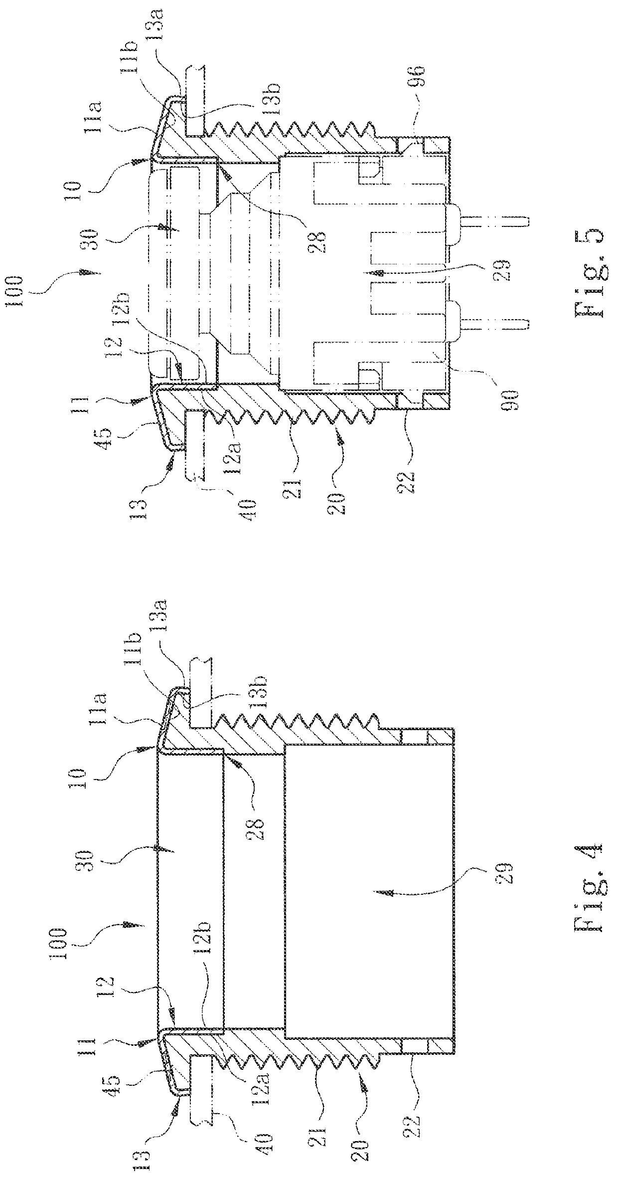
[0012]It is therefore a primary object of the present invention to provide a switch seat body structure including a main body for assembling with a switch component. The main body is composed of a metal head section in the form of a thin sheet structure and a nonmetal belly section. The main body is defined with an axis. The metal head section has a first wall normal to or inclined from the axis and a second wall connected with one end of the first wall and parallel to or inclined from the axis. The first and second walls together define a space therebetween. The nonmetal belly section fills the space to connect with entire sections of the first and second walls as an integrated body. In condition that the switch seat body can resist against the outward destroying force and the manufacturing process is simplified, the shortcomings of the conventional switch device that the processing and manufacturing operation is time-consuming and troublesome the material cost is higher are improved.
[0013]In the above switch seat body structure, the first and second walls of the metal head section (or the main body) contain an angle, which is an acute angle, a right angle or an obtuse angle. The first and second walls together define at least one shaft hole positioned on the axis. The shaft hole has a geometrical configuration. The second wall is formed with multiple assembling sections. The assembling sections have the form of protruding plate body structure or hole structure for enhancing the connection effect between the second wall and the nonmetal belly section.

Problems solved by technology

As well known by those who are skilled in this field, the manufacturing, assembling, processing and securing operation of the seat body of the above embodiment are more troublesome and time-consuming.
As a result, the manufacturing cost is increased.
For example, the substrate applies reaction force to the seat body to cause wear and damage of the surface structure of the seat body and make the seat body loosen from the substrate.
In this case, the problems of the conventional switch device that the manufacturing process is time-consuming and troublesome, a great amount of waste metal material is produced and the cost is higher are solved.

Method used


Image

  • Switch seat body structure
  • Switch seat body structure
  • Switch seat body structure

Examples


Embodiment Construction

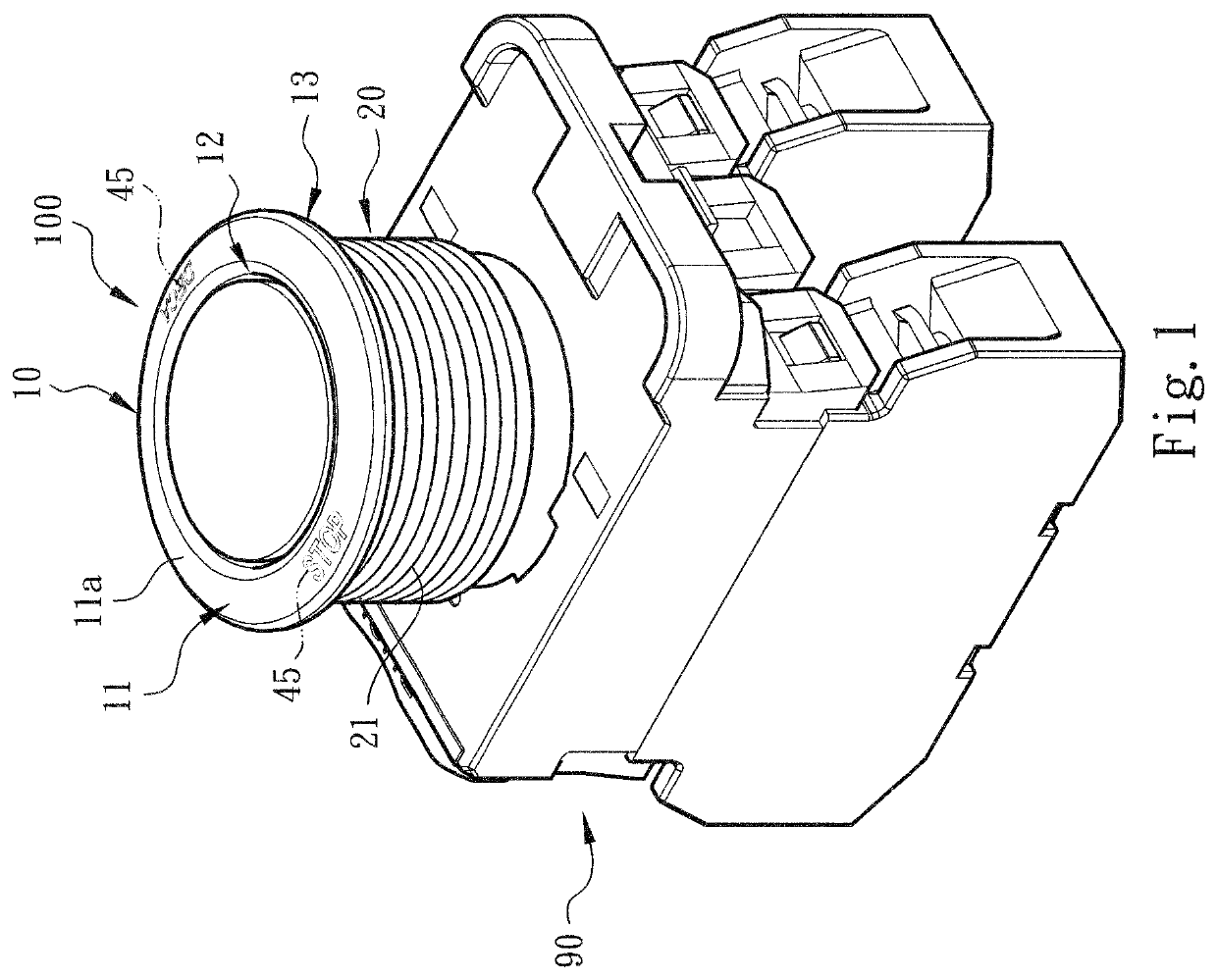
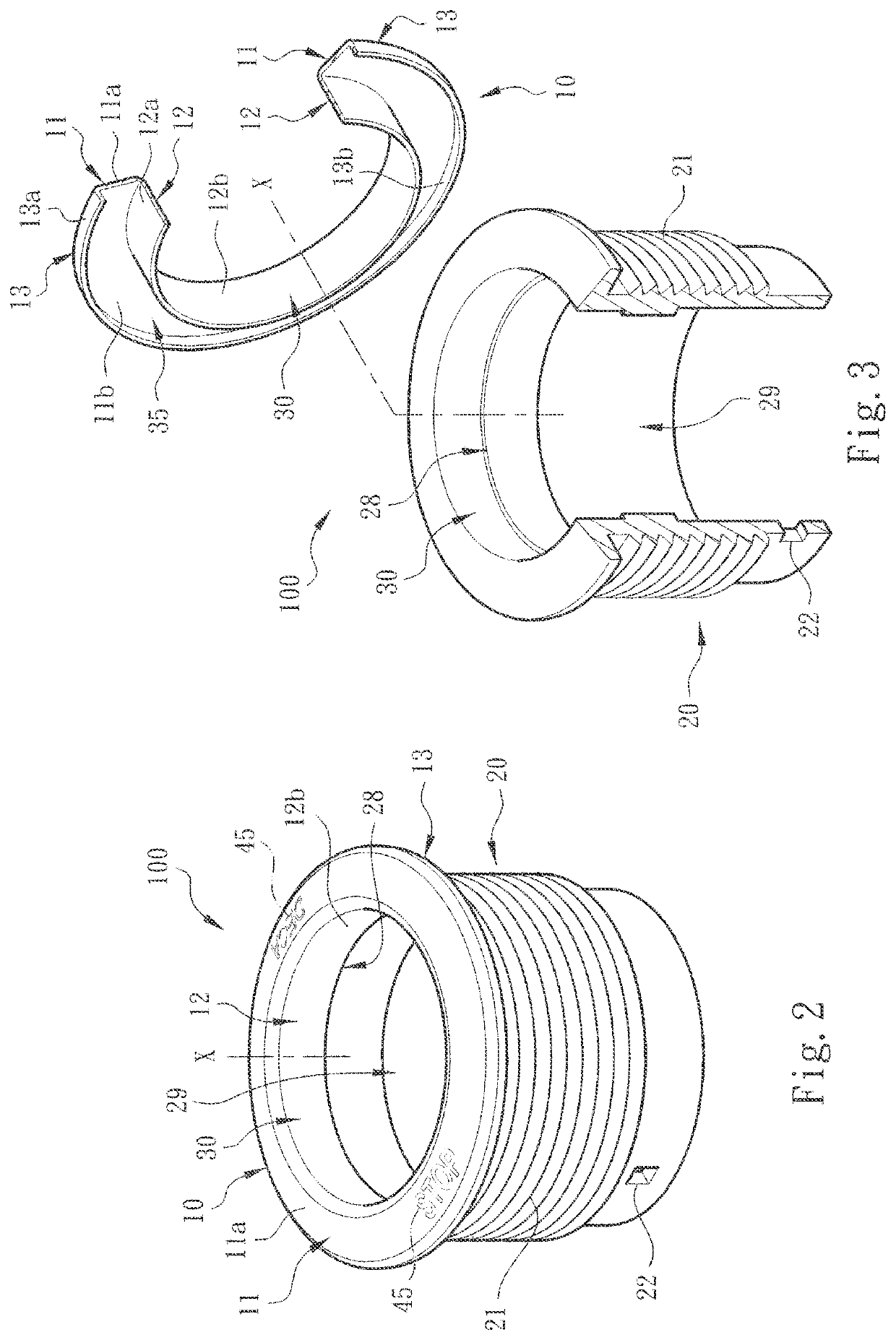
[0036]Please refer to FIGS. 1, 2 and 3. The switch seat body structure of the present invention includes a switch seat main body 100 for assembling with a switch component 90 (or wire connection terminal) to forma switch device or switch assembly. In a preferred embodiment, the main body 100 is composed of a metal head section 10 in the form of a thin sheet structure and a nonmetal belly section 20. The main body 100 is defined with an axis x.

[0037]In the description hereinafter, the upper section, upper side, lower section, lower side, outer section, outer side, inner section, inner side, etc. mentioned are recited with the direction of the drawings as the reference direction.

[0038]In a preferred embodiment, the metal head section 10 is made from a metal thin sheet by means of directly pressing the metal thin sheet. The metal head section 10 has a first wall 11 normal to (or inclined from) the axis x and a second wall 12 connected with one end of the first wall 11 in parallel to (o...


PUM


Abstract

A switch seat body structure includes a main body for assembling with a switch component. The main body is composed of a metal head section in the form of a thin sheet structure and a nonmetal belly section. The main body is defined with an axis. The metal head section has a first wall normal to or inclined from the axis and a second wall connected with the first wall and parallel to or inclined from the axis. The first and second walls together define a space. The nonmetal belly section fills the space to connect with entire sections of the first and second walls as an integrated body. The switch seat body assembling structure improves the problems that the processing and manufacturing processes are time-consuming and troublesome and the material cost is higher.

Description

BACKGROUND OF THE INVENTION1. Field of the Invention[0001]The present invention relates generally to a switch seat body structure, and more particularly to a switch seat body structure including a complex switch seat main body composed of a metal head section in the form of a thin sheet structure and a nonmetal belly section. The nonmetal belly section is connected with the metal head section as an integrated body.2. Description of the Related Art[0002]A conventional switch or switch indication device is applied to an electrical, electronic or automatic control system for an operator to know the working or power-on / off state of the machine. Such switch device includes a seat body or main body, internal switch components and multiple sets of terminal pins arranged in a chamber defined by the seat body. The terminal pins extend out of the chamber or the seat body to connect with electrical conductive wire or insert on a circuit board to achieve electrical connection. A light source is...

Claims


Application Information

Patent Timeline
Patent Type & Authority Patents(United States)
IPC IPC(8): H01H13/04H01H13/02
CPCH01H13/04H01H13/023H01H13/50H01H2239/038H02B1/044
Inventor WU, CHIH-YUANSUNG, CHIH-HAOHSU, CHIH-KAI
Owner SWITCHLAB
Learn More