Rotary position sensor and method of manufacturing the same

a technology of rotary position sensor and manufacturing method, which is applied in the direction of instruments, vehicle sub-unit features, transportation and packaging, etc., can solve problems such as errors in measured rotation angle, and achieve the effects of improving product life, improving product quality, and improving product li

Active Publication Date: 2022-03-22
SENSATA TECHNOLOGIES INC
View PDF9 Cites 0 Cited by
  • Summary
  • Abstract
  • Description
  • Claims
  • Application Information

AI Technical Summary

Benefits of technology

[0005]It is an object of the present technology to provide a rotary position sensor which is relatively easy to manufacture and has advantages over the known rotary position sensors such as: improved product lifetime; improved output accuracy over the product life; the robustness to withstand high fatigue strength requirements; and high magnetic immunity.
[0009]FIG. 3 shows a graph with two curves with the error due to eccentricity of the magnet on the Y-axis and the angle of the magnetic moment of the magnet on the X-axis. In one curve, the eccentricity is 0.3 mm and in the other curve the eccentricity is 0.6 mm. It could be seen that the absolute error is minimal near the angles −90°, 0°, 90° and maximal around −45° and 45°. During the lifetime of a rotation sensor, in particular an angle sensor of an ELC system, wear of the bearing will be greatest in a certain specific direction caused by the design of the apparatus in which the rotation sensor is used. In practice, this specific direction will normally correspond to the angle which is measured most often by the rotation sensor. Due to this wear, the rotation axis of the dipole magnet has the clearance to displace relative to the centre of the sensing-IC and consequently the di-pole magnet will be rotated eccentric with respect to the centre of the sensing-IC. If the direction of displacement is substantially parallel or perpendicular to the magnetic moment of the dipole magnet, the absolute error in the most often used angle of the sensor will be minimal. Thus, if the displacement, i.e. the direction of most wear, is not parallel or perpendicular to the magnetic moment of the dipole magnet, the measured value of the most often used angle will drift away from the real angle, resulting in an incorrect levelling of the apparatus. The current sensing-ICs do not require that the magnetic moment of the dipole magnet has a predetermined angle with respect to the sensing-IC to calibrate the rotation sensor. As a result of this, the orientation of the magnet on the shaft has not been known. However, according to the present technology, to reduce errors in the output signal due to wear of the bearing of the sensor, the sensor comprises a characteristic which is detectable on the outside of the sensor which indicates the magnetic moment of the dipole magnet. This allows a technician to position a rotary position sensor such in an apparatus that the direction of magnetic moment of the dipole magnet is substantially parallel with or perpendicular to the direction of most expected wear over the lifetime of rotary position sensor.
[0013]In a further embodiment, the shaft is press-fitted in the coupling element. This feature allows to use an simple manufacturing process to couple the coupling element and the shaft wherein the angel of rotation of the coupling element relative to the shaft could easily adapted depending on the application of the rotary position sensor to be manufactured.
[0014]In a further embodiment, a weld strengthens the connection between the coupling element and the shaft. This is advantageous in case a lever is attached to the coupling element and force parallel to the rotation axis of the first structure are acting on the lever.

Problems solved by technology

However, when the rotation axis of the di-pole magnet is not-aligned with the centre of the sensing-IC, there will be an error in the measured rotation angle due to eccentricity of the rotation axis of the di-pole magnet and centre of the sensing-IC.

Method used


Image

  • Rotary position sensor and method of manufacturing the same
  • Rotary position sensor and method of manufacturing the same
  • Rotary position sensor and method of manufacturing the same

Examples


Embodiment Construction

[0029]The advantages, and other features of the technology disclosed herein, will become more readily apparent to those having ordinary skill in the art from the following detailed description of certain preferred embodiments taken in conjunction with the drawings which set forth representative embodiments of the present technology.

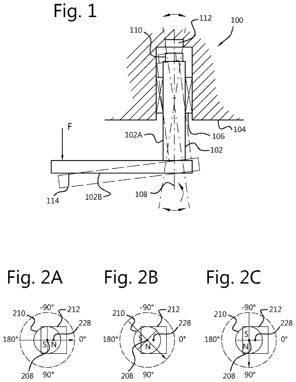
[0030]FIG. 1 shows schematically in a sectional view the effect of wear in a rotary position sensor. A rotary position sensor 100 is a sensor arrangement comprising a first structure 102 and a second structure 104. The first structure 102 is rotatably coupled to the second structure 104 by means of a bearing structure 106 having a rotation axis 108. The bearing structure may comprise one or more smaller bearings having the same rotation axis. A dipole magnet 110 is attached to the first structure with a direction of magnetic moment perpendicular to the rotation axis 108. A sensing unit 112 is attached to the second structure 104 and configured to measure ...


PUM


Abstract

A rotary position sensor is disclosed. The sensor comprises a first structure and a second structure. The first structure is rotatably coupled to the second structure by means of a bearing having a rotation axis. A dipole magnet is attached to the first structure with a direction of magnetic moment perpendicular to the rotation axis and a sensing unit is attached to the second structure and configured to measure the absolute position of the dipole magnet's rotation angle. The first structure comprises an alignment characteristic which is detectable on the outside of the rotary position sensor. The dipole magnet is attached to the first structure such that the alignment characteristic and direction of the magnetic moment of the dipole magnet have a defined angle of rotation relation on the first structure.

Description

TECHNICAL FIELD[0001]The subject disclosure relates to a rotary position sensor. The subject disclosure further relates to a method of manufacturing the rotary position sensor.BACKGROUND ART[0002]The height of the chassis of a truck or trailer is regulated by an Electronic Level Control (ELC) system. The ELC system comprises an angle sensor which is connected by means of two linkage bars to a wheel axle. The angle sensor is attached to the chassis of the vehicle. An end of a mainly vertical positioned linkage bar is coupled to the wheel axle. An end of a mainly horizontal positioned linkage bar is coupled to a rotation axis of the angle sensor. The other ends of the two linkage bars are coupled together by means of a hinge structure. When the wheel axis moves up / down relative to the chassis, this movement results in rotation of the rotation axis of the angle sensor. The angle sensor measures the angle of the rotation axis. The measured angle is indicative of the height of the vehicl...

Claims


Application Information

Patent Timeline
Patent Type & Authority Patents(United States)
IPC IPC(8): G01B7/30G01D5/14
CPCG01D5/145G01B7/30G01D5/12B62D21/02B60Y2400/301
Inventor ZWIJZE, ALBERT FERDINANDGENNISSEN, PAULUS THOMAS JOHANNESHENDRIKS, SIETSE ABEL MICHIEL
Owner SENSATA TECHNOLOGIES INC
Why Eureka
Try Eureka