Optical coupling device and optical communication system
a coupling device and optical communication technology, applied in the field of optical coupling devices and optical communication systems, can solve the problems of unsuitable short-range optical communication, and achieve the effect of excellent optical communication properties and efficient collection
- Summary
- Abstract
- Description
- Claims
- Application Information
AI Technical Summary
Benefits of technology
Problems solved by technology
Method used
Image


Examples
first embodiment
[0061]An optical coupling device according to a first embodiment and an optical module using the same will be described. Hereinafter, components similar to the above-described components are denoted by the similar signs, and the description may be omitted.
Optical Coupling Device
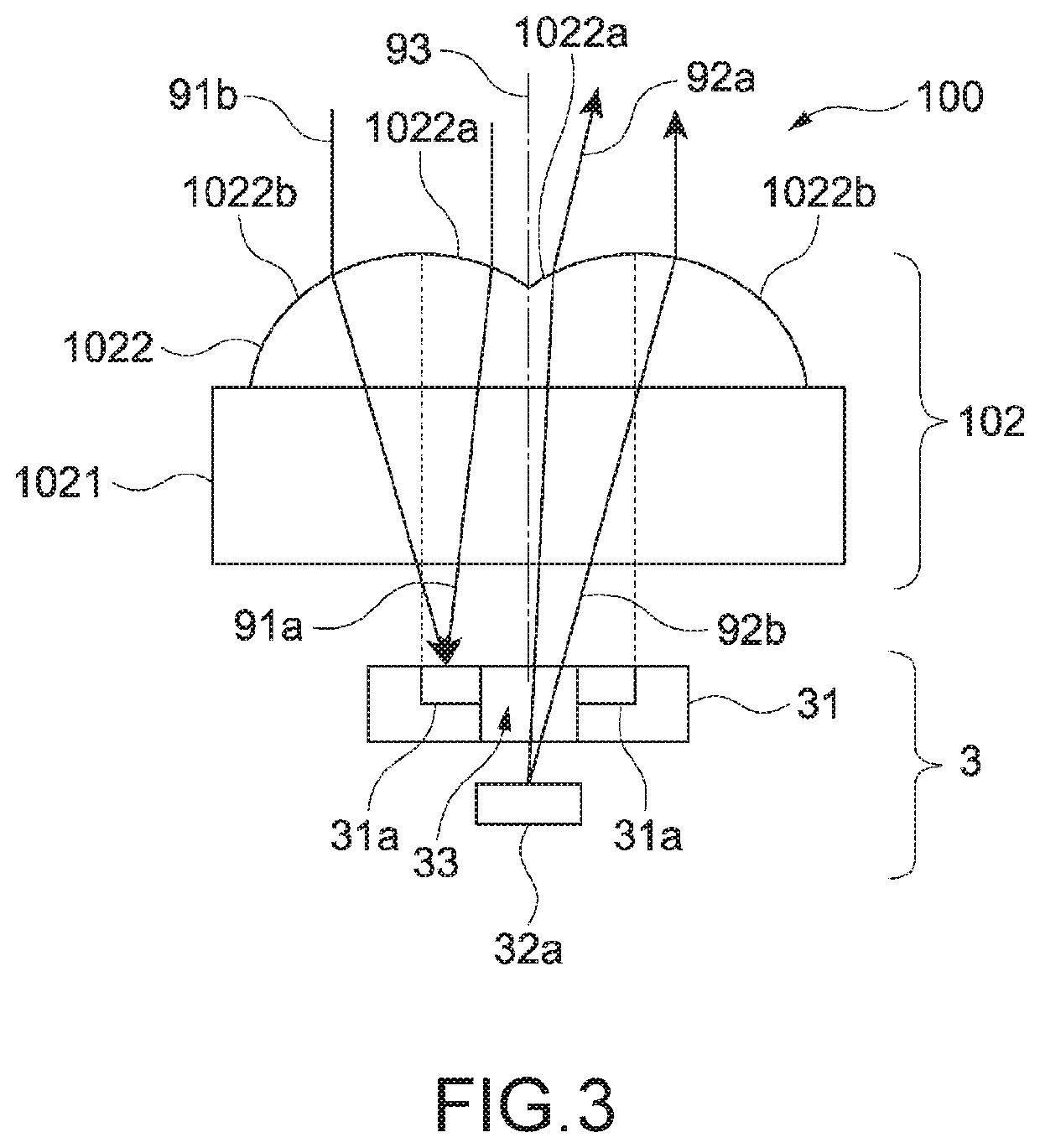
[0062]The optical coupling device according to the first embodiment will be described by using FIG. 3. FIG. 3 is a basic structure diagram of a main part of the optical coupling device according to the first embodiment.
[0063]As shown in FIG. 3, an optical coupling device 100 includes the light receiving and emitting device 3 and a lens substrate 102 as the optical device.
[0064]The lens substrate 102 includes a support substrate 1021 that is a transparent glass substrate through which light passes and a lens having two curves 1022 formed on one surface (surface positioned at optical fiber side upon communication) of the support substrate 1021. The lens having two curves 1022 is formed by resin molding, for exa...
second embodiment
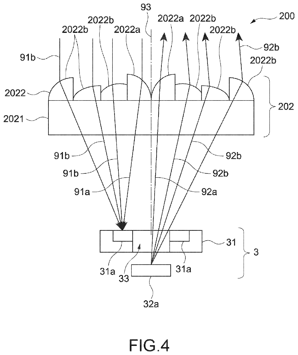
[0086]An optical coupling device according to a second embodiment will be described by using FIG. 4. FIG. 4 is a basic structure diagram of a main part of the optical coupling device according to the second embodiment. In the present embodiment, the structure of the optical device is different from that in the first embodiment. Hereinafter, components similar to the above-described components are denoted by the similar signs, and the description may be omitted.
[0087]As shown in FIG. 4, an optical coupling device 200 includes the light receiving and emitting device 3 and a Fresnel lens substrate 202 as the optical device.
[0088]The Fresnel lens substrate 202 includes support substrate 2021 that is a transparent support substrate through which light passes and a Fresnel lens 2022 formed on one surface of the support substrate 2021. Note that the support substrate 2021 and the Fresnel lens 2022 may be formed by monolithic injection molding with resin.
[0089]The Fresnel lens 2022 has a ce...
third embodiment
[0092]An optical coupling device according to a third embodiment will be described by using FIG. 5. FIG. 5 is a basic structure diagram of a main part of the optical coupling device according to the third embodiment. In the present embodiment, the structure of the optical device is different from that in the first embodiment. Hereinafter, components similar to the above-described components are denoted by the similar signs, and the description may be omitted.
[0093]As shown in FIG. 5, an optical coupling device 300 includes the light receiving and emitting device 3 and a refractive index distribution type lens 302 as the optical device.
[0094]The refractive index distribution type lens 302 is a lens having a cylindrical shape and a refractive index gradient in which a refractive index is changed in a radial direction (direction orthogonal to optical axis 93). In FIG. 5, magnitude of the refractive index is represented by dark and light using dots. The darker the color is, the higher t...
PUM
| Property | Measurement | Unit |
|---|---|---|
| angle | aaaaa | aaaaa |
| angle | aaaaa | aaaaa |
| optical path | aaaaa | aaaaa |
Abstract
Description
Claims
Application Information
 - R&D
- Intellectual Property
- Life Sciences
- Materials
- Tech Scout
- Unparalleled Data Quality
- Higher Quality Content
- 60% Fewer Hallucinations
Browse by: Latest US Patents, China's latest patents, Technical Efficacy Thesaurus, Application Domain, Technology Topic, Popular Technical Reports.
© 2025 PatSnap. All rights reserved.Legal|Privacy policy|Modern Slavery Act Transparency Statement|Sitemap|About US| Contact US: help@patsnap.com