Control device, control method, and storage medium

a control device and control method technology, applied in the field of control devices, can solve the problems of insufficient maintainability, inability to change a time period, and inability to obtain control stability obtained by flexibly reflecting high frequency feedback information of external recognition devices, and achieve the effect of robust stability and maintainability

Active Publication Date: 2022-05-03
KK TOSHIBA
View PDF16 Cites 0 Cited by
  • Summary
  • Abstract
  • Description
  • Claims
  • Application Information

AI Technical Summary

Benefits of technology

[0005]The present invention has been made to solve the aforementioned problems, and an object of the present invention is to provide a control device, a control method, and a storage medium, by which more robust stability and maintainability are achieved.

Problems solved by technology

In such a general-purpose controller, even when the performance of the external recognition devices is improved such that the feedback information of the external recognition devices is output at a higher frequency, there are cases where it is not possible to change a time period at which the general-purpose controller accepts the recognition results from external recognition devices.
In such a case, in a situation in which high real-time characteristics are required, there are cases where it is not possible to quickly reflect the latest recognition results or sensing results in a command value output from the general-purpose controller to the robot.
As a consequence, there are cases where control stability obtained by flexibly reflecting high frequency feedback information of the external recognition devices is not obtained.
Moreover, in the related general-purpose controller, since it is difficult to modify software due to problems of compatibility and the like, there are cases where maintainability is not sufficient.

Method used


Image

  • Control device, control method, and storage medium
  • Control device, control method, and storage medium
  • Control device, control method, and storage medium

Examples


first embodiment

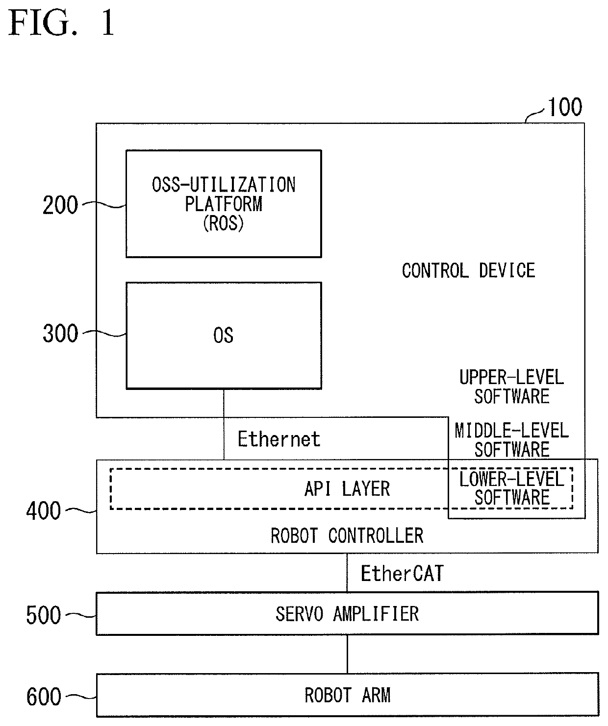
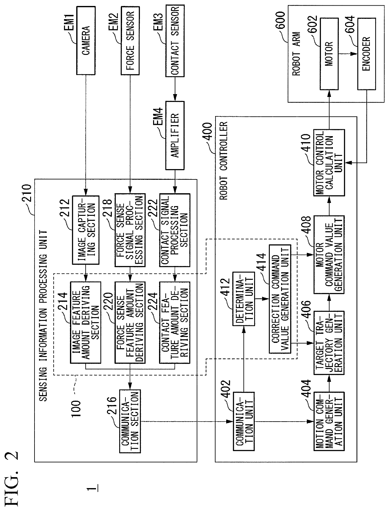
[0021]FIG. 1 is a schematic diagram illustrating a usage environment of a control device 100 of a first embodiment. Hereinafter, an example in which an autonomous motion mechanism controlled by the control device 100 is a robot arm device 600 will be described.

[0022]The robot arm device 600, for example, is controlled by the control device 100, an open source software (OSS)-utilization platform 200, an operating system (OS) 300, a robot controller 400, and a servo amplifier 500 in cooperation. The control device 100, the OSS-utilization platform 200, and the OS 300 are opened in a memory such that they can be executed by at least one processor (for example, a central calculation control device or a central processing unit (CPU)). The robot controller 400 may be logically opened in the same device as the OSS-utilization platform 200 and the OS 300, or may be logically opened in a device different from the OSS-utilization platform 200 and the OS 300.

[0023]The control device 100, for e...

second embodiment

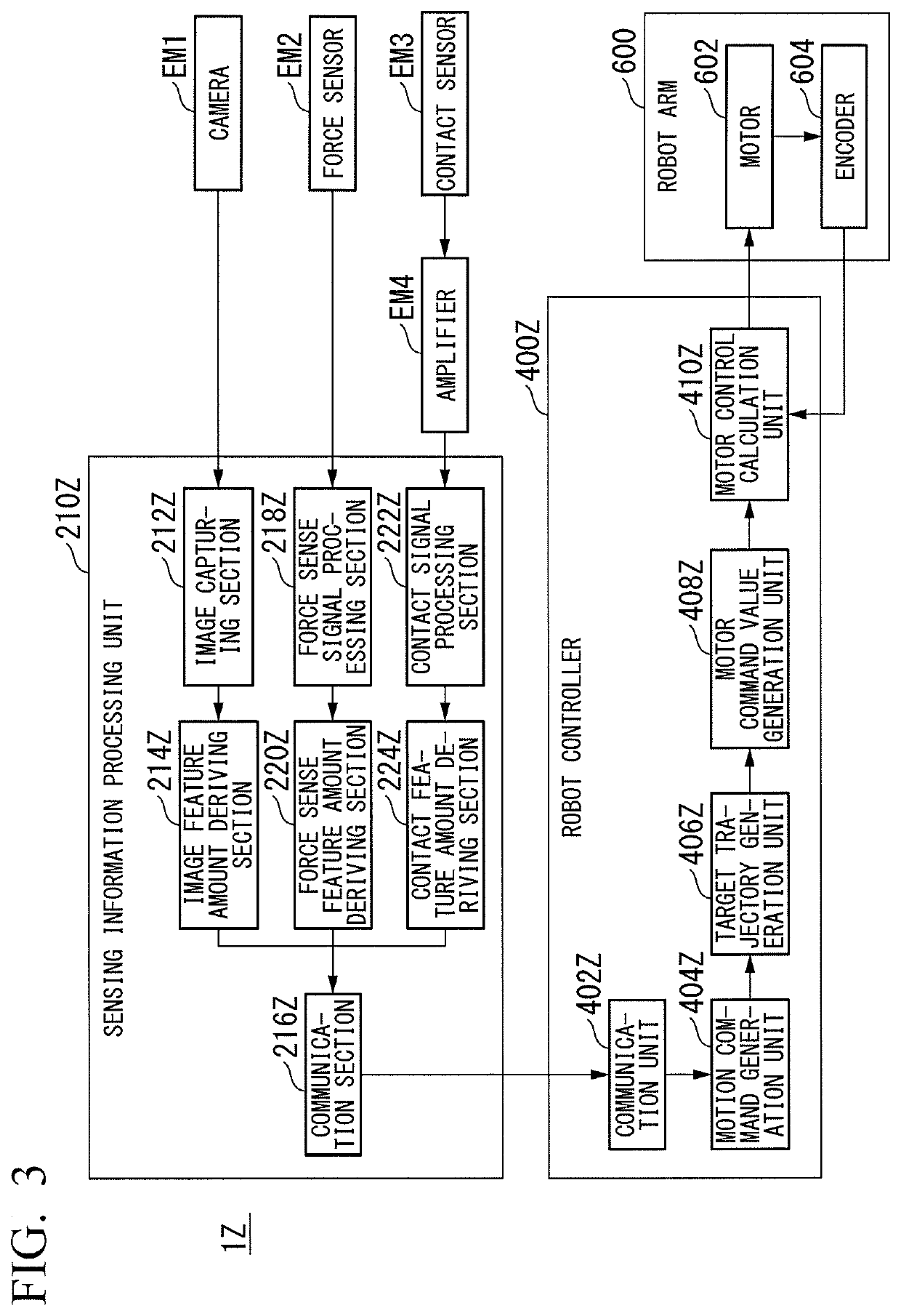
[0055]Next, a control system 1A of a second embodiment will be described. In the following description, elements having the same functions as the content described in the first embodiment are denoted by the same names and reference numerals, and a detailed description of the functions will be omitted. The same applies to other embodiments to be described later.

[0056]FIG. 6 is a block diagram illustrating an example of a configuration of the control system 1A of the second embodiment. The control system 1A of FIG. 6 is different from the control system 1 of FIG. 2 in that a motion planning unit 150 is further provided, the motion command generation unit 404 is removed, and the motor control calculation unit 410 is replaced with a servo driver 510. Consequently, the motion planning unit 150 and the servo driver 510 will be mainly described below. The motion planning unit 150, for example, is implemented by the middle-level software executed on the OSS-utilization platform 200 or the O...

third embodiment

[0069]Next, a control system 1B of a third embodiment will be described.

[0070]FIG. 9 is a block diagram illustrating an example of a configuration of the control system 1B of the third embodiment. The control system 1B of FIG. 9 is different from the control system 1A of FIG. 6 in terms of a distance sensor EM7, an optical sensor EMB, elements of a sensing information processing unit 210B, and elements of a motion planning unit 150B. Consequently, the difference with the control system 1A will be mainly described below. A three-dimensional point cloud generation section 230, a feature amount deriving section 232, and an optimization computation section 234 are implemented by the upper-level software executed on the OSS-utilization platform 200 illustrated in FIG. 1.

[0071]The distance sensor EM7, for example, is installed at the distal end and the like of the grasping member of the robot arm device 600 and measures a distance between an object to be grasped recognized by the camera E...


PUM


Abstract

A control device includes at least two processors comprising at least a first processor and a second processor. The control device controls at least one autonomous motion mechanism on the basis of a recognition result received from a recognition device. A storage device of the control device stores upper-level software, middle-level software, and lower-level software. The upper-level software derives a feature amount representing a feature of the recognition result. The middle-level software generates a motion plan of the autonomous motion mechanism on the basis of the feature amount. The lower-level software outputs a command value for controlling the autonomous motion mechanism on the basis of the motion plan. The first processor executes at least the upper-level software, the second processor executes at least the lower-level software, and at least one processor included in the control device executes the middle-level software.

Description

CROSS-REFERENCE TO RELATED APPLICATION[0001]Priority is claimed on Japanese Patent Application No. 2018-150220, filed Aug. 9, 2018, the content of which is incorporated herein by reference.BACKGROUNDField of the Invention[0002]An embodiment of the present invention relates to a control device, a control method, and a storage medium.Description of Related Art[0003]A general-purpose controller, which controls the position, orientation, and the like of a robot on the basis of recognition results from external recognition devices (for example, information on images captured by cameras or sensing results from sensors), is provided by robot manufacturers and the like. The general-purpose controller accepts the input of feedback information obtained from image recognition results, sensing results and the like only at a fixed time period (for example, 30 [milliseconds]) in many cases.[0004]In such a general-purpose controller, even when the performance of the external recognition devices is...

Claims


Application Information

Patent Timeline
Patent Type & Authority Patents(United States)
IPC IPC(8): B25J9/16G06F9/30
CPCB25J9/1664G06F9/3004G05B2219/40G05B19/0421
Inventor OOGA, JUNICHIROOGAWA, AKIHITO
Owner KK TOSHIBA
Why Eureka
Try Eureka