Fuel cell system
a fuel cell and system technology, applied in the field of fuel cell systems, can solve the problems of deteriorating the power generation performance of fuel cells
- Summary
- Abstract
- Description
- Claims
- Application Information
AI Technical Summary
Benefits of technology
Problems solved by technology
Method used
Image
Examples
first embodiment
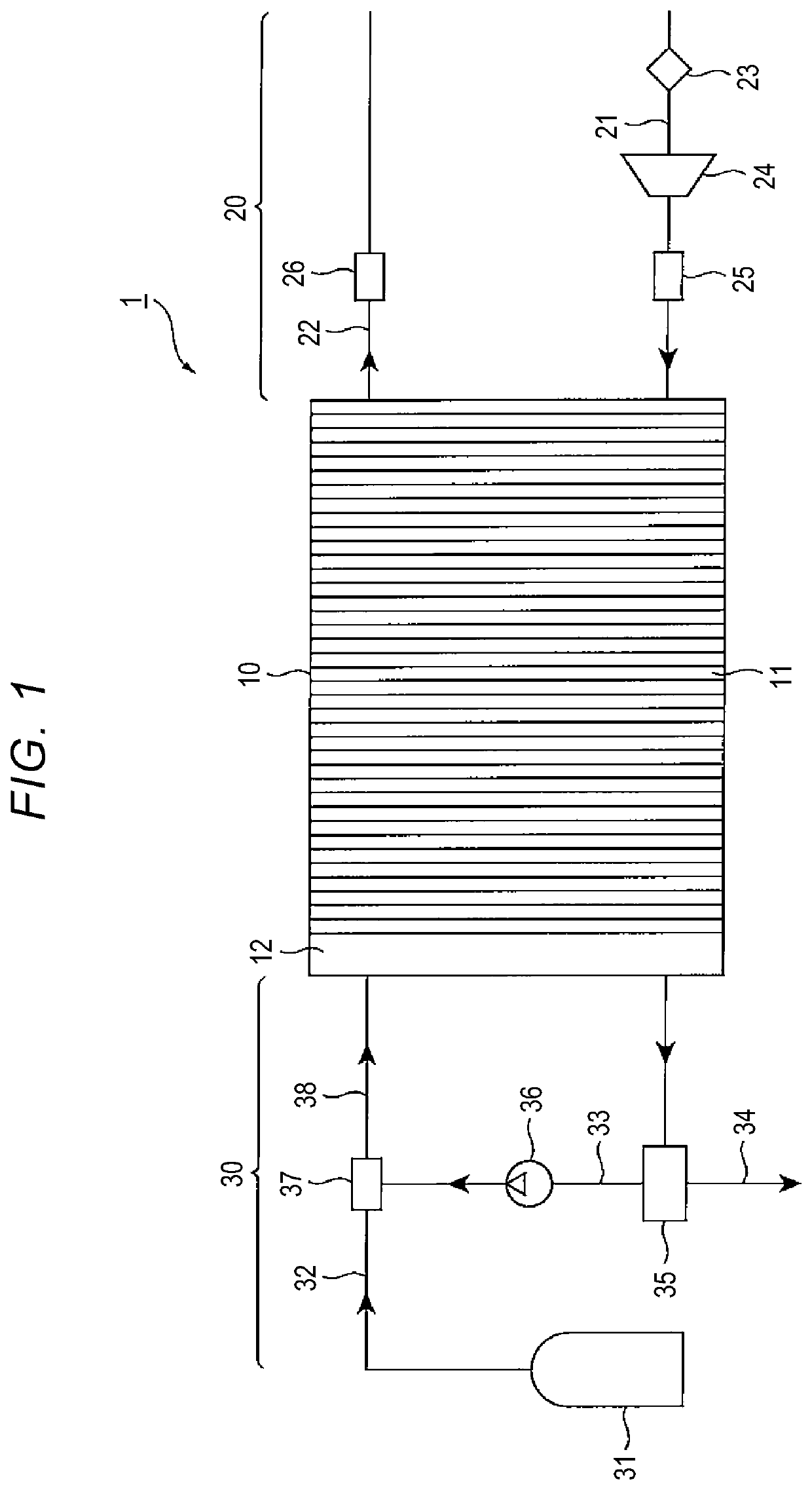
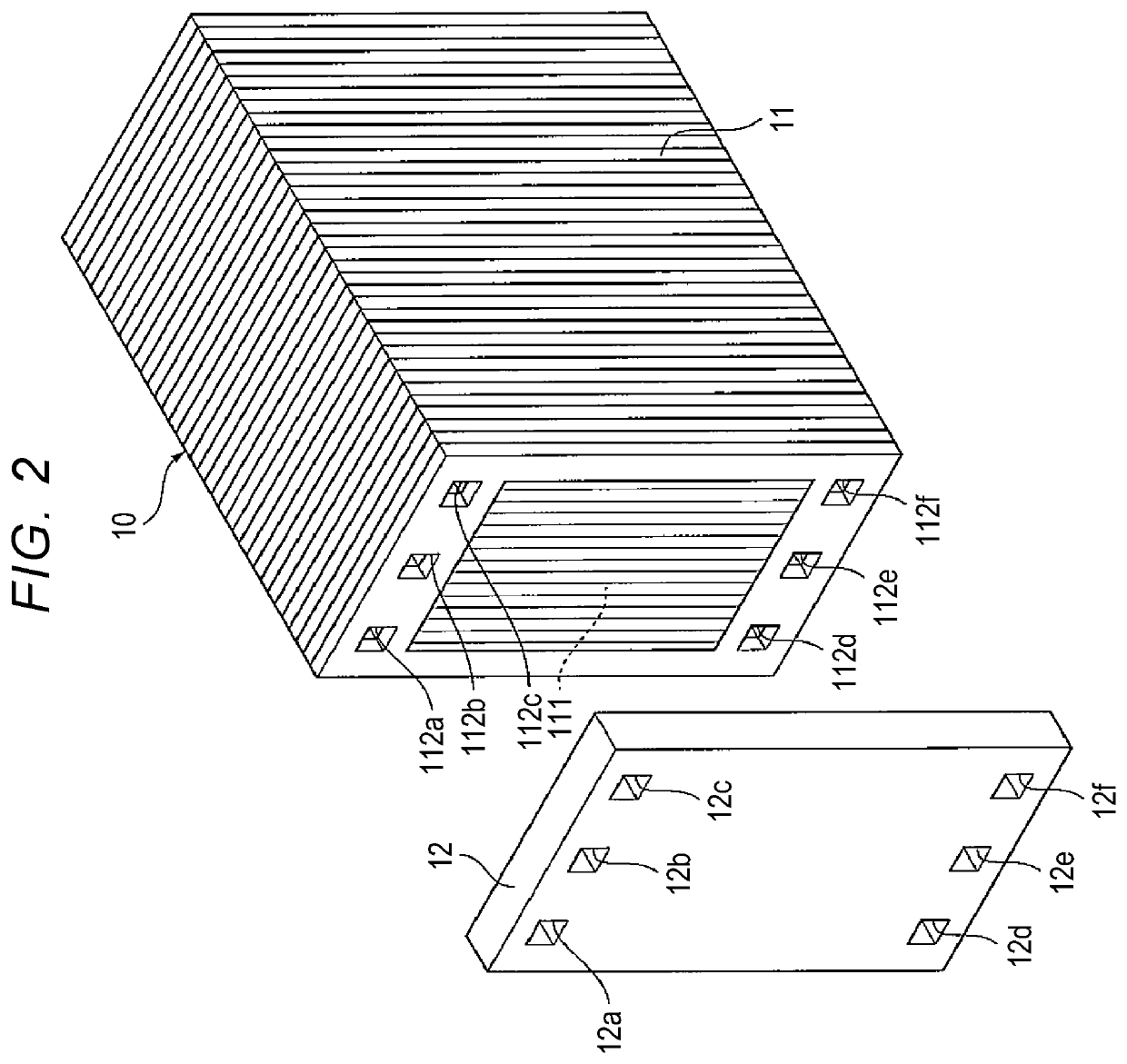
[0024]FIG. 1 is a schematic configuration diagram of a fuel cell system according to a first embodiment. FIG. 2 is a perspective view illustrating a fuel cell stack and a stack manifold. A fuel cell system 1 of the present embodiment includes, as main components, a fuel cell stack 10, an oxidant gas supply system 20 that supplies an oxidant gas, such as air, to the fuel cell stack 10, and a fuel gas supply system 30 that supplies a fuel gas, such as hydrogen, to the fuel cell stack 10.
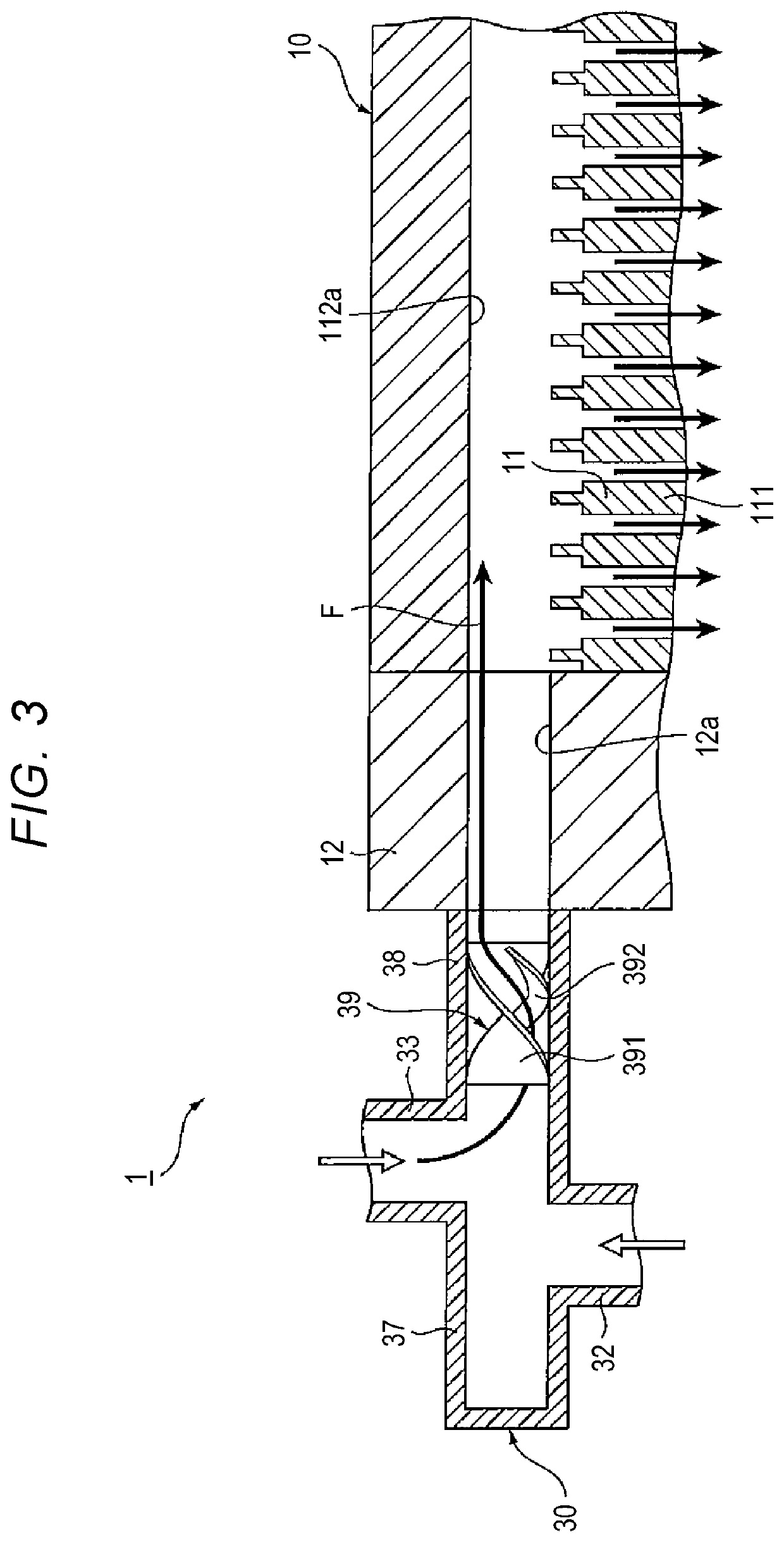
[0025]The fuel cell stack 10 is a cell stack including a plurality of fuel cells 11 that are stacked. The fuel cell stack 10 is a solid polymer electrolyte fuel cell. Although not illustrated, each of the fuel cells 11 includes a membrane electrode assembly (MEA) including, for example, an ion-permeable electrolyte membrane, and an anode catalyst layer (an anode electrode) and a cathode catalyst layer (a cathode electrode) between which the electrolyte membrane is held. Each fuel cell 11 further includ...
second embodiment
[0043]Hereinafter, a fuel cell system according to a second embodiment will be described with reference to FIG. 5A and FIG. 5B. FIG. 5A is a plan view of an agitation mixer 39A according to the second embodiment. FIG. 5B is a sectional view taken along line VB-VB in FIG. 5A. Although the fuel cell system according to the present embodiment is different from that of the first embodiment in the shape of the guide rib of the agitation mixer, the other configurations are the same as those of the first embodiment. Therefore, detailed description of the same configurations as those in the first embodiment will be omitted.
[0044]Specifically, as illustrated in FIG. 5A, the agitation mixer 39A includes a mixer body 391 having a spiral shape, and a guide rib 393. The mixer body 391 is formed by, for example, twisting a single thin plate. The guide rib 393 is provided along the spiral shape of the mixer body 391. The guide rib 393 extends over the entire length of the mixer body 391 such that ...
PUM
| Property | Measurement | Unit |
|---|---|---|
| swirling force | aaaaa | aaaaa |
| shape | aaaaa | aaaaa |
| length | aaaaa | aaaaa |
Abstract
Description
Claims
Application Information
 - R&D
- Intellectual Property
- Life Sciences
- Materials
- Tech Scout
- Unparalleled Data Quality
- Higher Quality Content
- 60% Fewer Hallucinations
Browse by: Latest US Patents, China's latest patents, Technical Efficacy Thesaurus, Application Domain, Technology Topic, Popular Technical Reports.
© 2025 PatSnap. All rights reserved.Legal|Privacy policy|Modern Slavery Act Transparency Statement|Sitemap|About US| Contact US: help@patsnap.com


