Curved surface processing method for inlet edge of cylindrical blade of centrifugal pump impeller

a centrifugal pump and inlet edge technology, which is applied in the direction of pump components, non-positive displacement fluid engines, liquid fuel engine components, etc., can solve the problems of increased mold making and casting costs, difficult actual manufacturing, etc., and achieves the reduction of the inlet angle at the top of the blade, easy to draft, and improve the adaptability of the inlet edge

Active Publication Date: 2022-05-17
JIANGSU UNIV
View PDF10 Cites 0 Cited by
  • Summary
  • Abstract
  • Description
  • Claims
  • Application Information

AI Technical Summary

Benefits of technology

[0009]In order to solve the aforementioned technical problems, the present invention provides a curved surface processing method for an inlet edge of a cylindrical blade of a centrifugal pump impeller. A top curve is extended in a tangential direction to decrease a blade angle. A curved surface of an inlet edge formed between the modified top curve and bottom curve has a twisted shape, but remains a cylindrical blade, which does not affect the mold and casting or injection molding production. Moreover, the inlet edge of the blade using the present method adapts to an incoming flow direction angle to a greater extent, which can improve the performance of the impeller.
[0019]The present invention achieves the following technical effects over the prior art.
[0020]In the curved surface processing method for the inlet edge of the cylindrical blade of the centrifugal pump impeller in the present invention, the angle of the inlet edge at the top of the blade is allowed to be more tangential, and thus the inlet angle at the top of the blade is reduced. A twisted surface is formed between the first arc segment R1 at the top and the second arc segment R2 at the bottom. This twisting feature is beneficial to improve the adaptability of the inlet edge of the blade to flowing of the incoming flow. Meanwhile, the blade with the newly-constructed inlet edge is still the cylindrical blade, and is easy to draft.

Problems solved by technology

However, the double-curvature blades are spatially twisted, which brings difficulties to actual manufacturing and increases costs of mold making and casting.
However, the use of cylindrical blades inevitably causes inadaptation of an inlet edge of a blade to an incoming flow angle, which usually results in an efficiency that is several percentage points lower than that of the impellers with twisted blades.

Method used


Image

  • Curved surface processing method for inlet edge of cylindrical blade of centrifugal pump impeller
  • Curved surface processing method for inlet edge of cylindrical blade of centrifugal pump impeller
  • Curved surface processing method for inlet edge of cylindrical blade of centrifugal pump impeller

Examples


embodiment 1

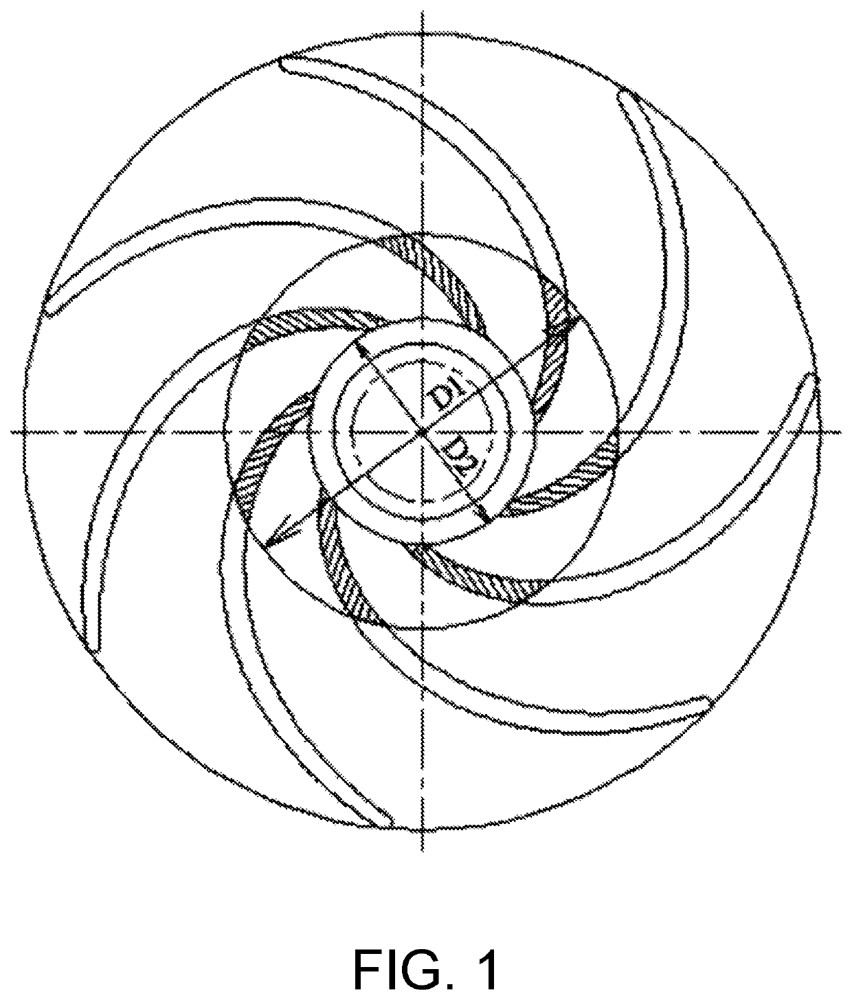
[0029]As shown in FIG. 1, this embodiment provides a curved surface processing method for an inlet edge of a cylindrical blade of a centrifugal pump impeller, and the method includes the following steps.

[0030]Step 1: A center of an impeller with existing cylindrical blades is used as a center to draw s first circle having a first diameter D1 and a second circle having a second diameter D2. The first circle having the first diameter D1 is an improved inlet position at a top of the blade, and the second circle having the second diameter D2 is an improved inlet position at a bottom of the blade.

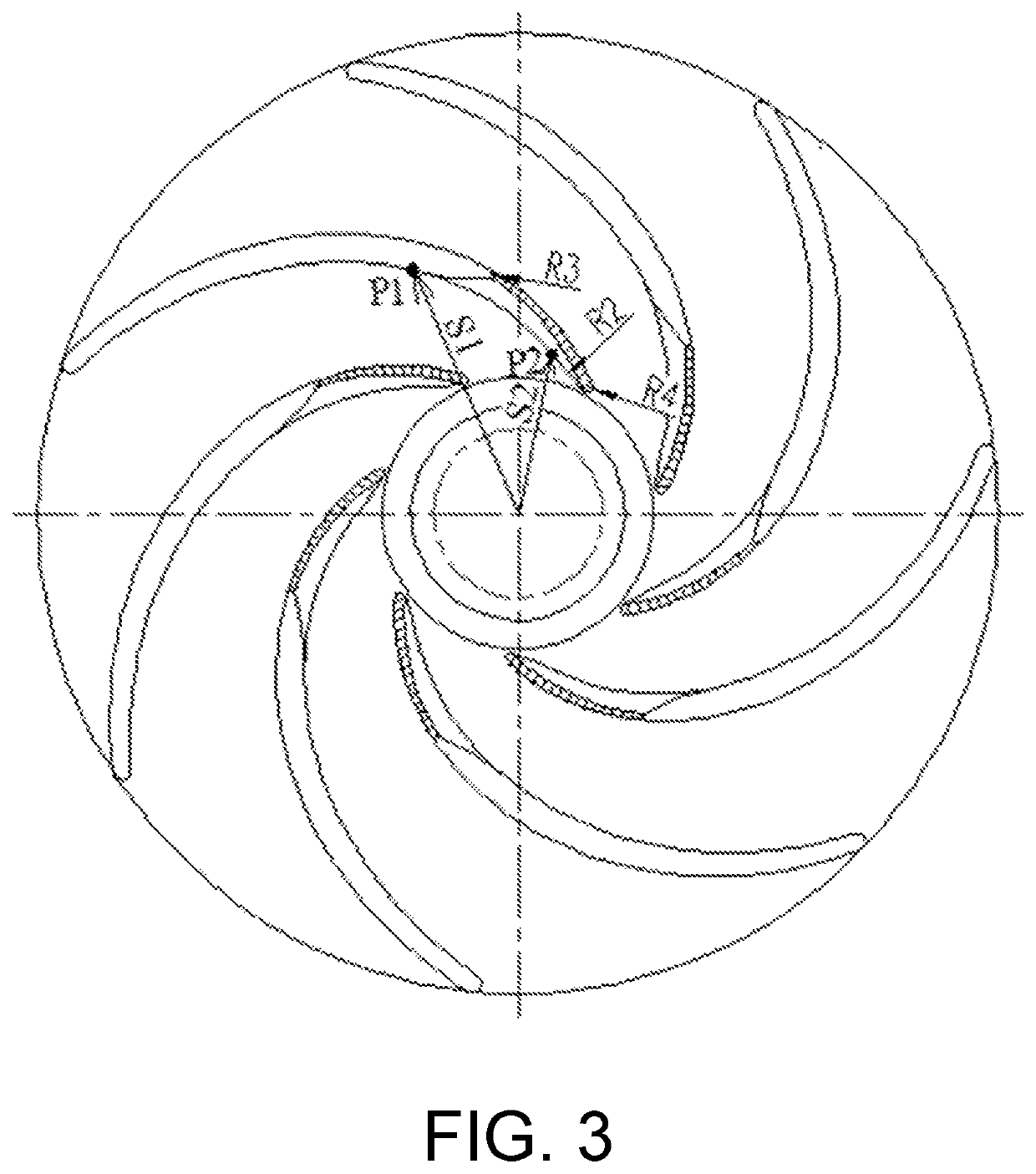
[0031]Step 2: A first point P1 having a first distance S1 from the center is determined on a concave side curve 5 at the top of the existing cylindrical blade, where the first distance S1=(1.1-1.3)×(D1) / 2. A second point P2 having a second distance S2 from the center is determined on a concave side curve 7 at the bottom of the blade, where the second distance S2=(1.1-1.3)× (D2) / 2.

[0032]Step 3: T...


PUM


Abstract

A curved surface processing method for an inlet edge of a cylindrical blade of a centrifugal pump impeller includes following steps. A center of an impeller is used as a center to draw circles having respective diameters. A first point having a first distance from the center is determined on a concave side curve at a top of the blade, and a second point having a second distance from the center is determined on a concave side curve at a bottom of the blade. By improving the shape of a blade in an impeller, the angle of an inlet edge at the top of the blade is more close to the tangent direction, and the inlet angle of the top blade is reduced. A twisted surface is formed between a first arc segment at the top and a second arc segment at the bottom.

Description

CROSS-REFERENCE TO RELATED APPLICATION[0001]This application is a 371 of international application of PCT application serial no. PCT / CN2020 / 090769, filed on May 18, 2020, which claims the priority benefit of China application no. 201910455788.8, filed on May 29, 2019. The entirety of each of the above mentioned patent applications is hereby incorporated by reference herein and made a part of this specification.BACKGROUNDTechnical Field[0002]The present invention relates to the technical field of centrifugal pump impellers, and particularly to a curved surface processing method for an inlet edge of a cylindrical blade of a centrifugal pump impeller.Description of Related Art[0003]In the past, there was little focus on the issue of the design process of a blade inlet in the design of a centrifugal pump with cylindrical blades. In the design of a cylindrical blade, a top curve and a bottom curve of the blade coincide with each other. In the actual design, only one concave side curve an...

Claims


Application Information

Patent Timeline
Patent Type & Authority Patents(United States)
IPC IPC(8): F04D29/24F04D29/22
CPCF04D29/22F04D29/2216F04D29/242F04D29/2222F05D2240/303
Inventor ZHANG, QIHUAKANG, SHUNZHANG, WEIDONGYAN, ZHAOXU
Owner JIANGSU UNIV
Why Eureka
Try Eureka