
Method for manufacturing a light-alloy hybrid wheel including a front flange and a rim

a technology of hybrid wheels and front flanges, which is applied in the direction of manufacturing tools, non-electric welding apparatus, transportation and packaging, etc., can solve the problems of long and costly operations, high cost of forging steps, and too large wheel weight in relation to current requirements

Active Publication Date: 2022-05-24
SAINT JEAN INDS
View PDF26 Cites 0 Cited by
  • Summary
  • Abstract
  • Description
  • Claims
  • Application Information

AI Technical Summary

Benefits of technology

The invention relates to a process called friction welding using a pin, which is also known as "FSW". This process can weld non-weldable or difficult-to-weld materials like aluminum without forming bubbles. It also results in better mechanical properties, including better strength and fatigue resistance, compared to conventional techniques. The process is simplified compared to previous methods and allows for greater variety in flange designs. The wheel made using this process has greater weight gain and impact resistance than traditional foundry made wheels.

Problems solved by technology

Known for example is the implementation of a wheel with a monoblock rim and flange obtained by molding, but requiring complex and costly technical means and recovering very substantial thickness dimensions, resulting in the weight of the wheel thus obtained being too great in relation to current requirements.
However, the implementation of this process causes some drawbacks in relation to new market requirements which are for example to obtain a reduction in the weight of products in the order of 20 to 30% while maintaining a competitive price.
These operations are long and costly.
This forging step is expensive, especially for small series wherein the manufacturing of these forging dies has a significant impact upon cost.
This shape, which extends over the entire circumference of the part, allows for a reduction in weight but the drilling and positioning of the valve are difficult to implement with this configuration.
However, the machining of these recesses is a long and expensive operation.
Thus, according to the aforementioned prior art, existing solutions for the implementation of recesses within the tire bead seat require significant metal removal and are therefore costly and time-consuming.

Method used


Image

  • Method for manufacturing a light-alloy hybrid wheel including a front flange and a rim
  • Method for manufacturing a light-alloy hybrid wheel including a front flange and a rim

Examples


Embodiment Construction

[0050]In order to render the object of the invention more concrete, it is herein described in a non-limiting manner and illustrated in the figures of the drawings.

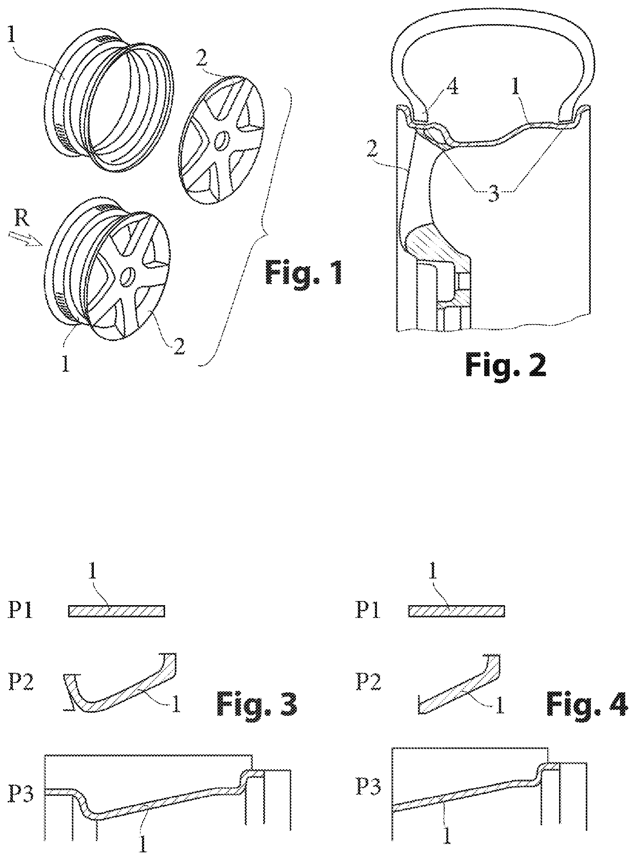
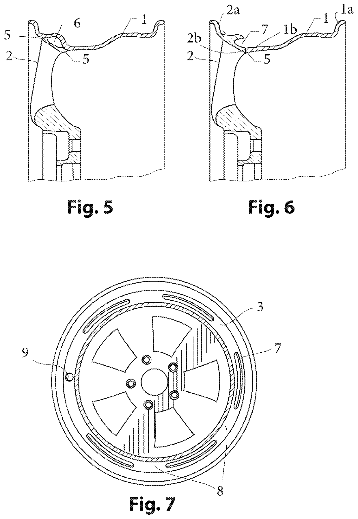
[0051]As previously noted, the profile of the rim (1) is simplified by the execution of a single weld (5) for the assembly thereof with the flange (2). The rim (1) has a circular profile (la) that acts as a seat for the tire but only on the inside of the wheel. The other profile (2a), acting as a seat for the tire, is implemented by the flange (2).

[0052]Hereinafter are highlighted certain features and advantages of the process of the invention.

[0053]FIGS. 3 and 4 illustrate the steps for obtaining the rim (1), according to the prior art and the invention respectively.

[0054]Within the scope of the invention, the rim (1) is made according to an operation (P1) of the production of a blank in the form of circular flank (1b); then an operation (P2) of expanding said circular flank (1b) to the dimensions of the final rim (1) in ...


PUM

PropertyMeasurementUnit
sizeaaaaaaaaaa
thicknessaaaaaaaaaa
weightaaaaaaaaaa

Abstract

The present disclosure provides a process for manufacturing a light-alloy hybrid wheel comprising the following separate operation phases: obtaining a front flange with an internal profile including a tire bead seat; obtaining a rim with an annular profile including a tire bead seat at a first end and a circular flank for assembly with a part of the flange at a second end; and assembling the flange and the rim to form a wheel. The annular profiles of the flange and the rim form exterior and interior sides of the wheel. Assembling the flange and the rim comprises welding the flank of the rim and the flange together by a single friction stir weld using a pin such that the weld is exposed at the exterior and interior sides of the wheel.

Description

CROSS REFERENCE TO RELATED APPLICATIONS[0001]This application is the National Phase filing under 35 U.S.C. § 371 of International Application No. PCT / FR2015 / 053590, filed on Dec. 17, 2015, and published on Jun. 23, 2016 as WO / 2016 / 097628A1, and claims priority to French Application No. 1462671, filed on Dec. 17, 2014. The contents of each of the prior applications are hereby incorporated by reference herein in their entirety.BRIEF SUMMARY OF THE INVENTION[0002]The invention relates to the technical sector of wheels, particularly for vehicles, motor vehicles, and also to the foundry and forging sectors for the manufacture of parts in light alloy, for example based upon aluminum or magnesium, designed particularly for the automotive industry.[0003]Known for example is the implementation of a wheel with a monoblock rim and flange obtained by molding, but requiring complex and costly technical means and recovering very substantial thickness dimensions, resulting in the weight of the whe...

Claims


Application Information

Patent Timeline
Patent Type & Authority Patents(United States)
IPC IPC(8): B60B3/04B21D53/30B60B21/02B21D22/16B22F3/10B23K20/12B23K26/28
CPCB60B3/041B21D22/16B21D53/30B22F3/10B23K20/122B23K26/28B60B3/044B60B3/045B60B21/02B60B2310/202B60B2310/208B60B2310/214B60B2310/228B60B2310/3025B60B2310/3026B60B2360/104B60B2900/112B60B2360/108B60B2310/204B60B3/04B23K20/12
Inventor DI SERIO, EMILE THOMASDUPERRAY, LIONEL
Owner SAINT JEAN INDS
Learn More