Electric drive device for vehicle

a technology for electric drive devices and vehicles, applied in the direction of electric propulsion mounting, braking systems, braking components, etc., can solve the problems of large device size, large size of electric drive devices for vehicles, and reducing the size of devices, so as to improve the weight balance of electric drive devices, reduce weight, and improve the effect of strength

Active Publication Date: 2022-05-31
TOYOTA JIDOSHA KK
View PDF13 Cites 0 Cited by
  • Summary
  • Abstract
  • Description
  • Claims
  • Application Information

AI Technical Summary

Benefits of technology

[0005]According to the disclosure, it is possible to eliminate the propeller shaft by a novel arrangement of the retarder.
[0007]In the above configuration, the rotating machine and the retarder are arranged on the opposite sides of the axis of the differential device in the front-rear direction of the vehicle in the plan view seen from above the vehicle, which improves a weight balance of the electric drive device for a vehicle, between parts forward and rearward of the axis of the differential device. Accordingly, it is possible to eliminate a propeller shaft and to form a compact electric drive device including the rotating machine, the retarder, and the differential device, which is advantageous in terms of space. In other words, if the weight balance is poor, it is necessary to increase strength, rigidity, etc. of various parts, which hinders downsizing.
[0009]In the above configuration, since both the rotating machine and the retarder are arranged parallel to the front-rear direction of the vehicle, dimensions of the electric drive device in the width direction of the vehicle can be reduced.
[0011]In the above configuration, the first rotating machine and the second rotating machine are provided as the rotating machine. The combined power transmission shaft to which the power output from the first rotating machine and the power output from the second rotating machine are transmitted is provided on the axis that is different from the axes of the first rotating machine and the second rotating machine. The retarder is disposed on the combined power transmission shaft. The combined power transmission shaft receives the power transmitted from the first rotating machine and the second rotating machine, and thus originally has high strength and rigidity. Thus, the retarder can be arranged on the combined power transmission shaft without any special reinforcement, etc. and a predetermined braking force can be generated by the single retarder. Accordingly, it is possible to eliminate a propeller shaft and to form a compact electric drive device including the first rotating machine, the second rotating machine, the retarder, and the differential device, which is advantageous in terms of space.
[0014]In the above configuration, the first rotating machine, the second rotating machine, and the combined power transmission shaft are all arranged parallel to the width direction of the vehicle, and the combined power transmission shaft on which the retarder is provided is the pinion shaft. Thus, dimensions of the electric drive device in the front-rear direction of the vehicle can be reduced, and thus, the electric drive device can be made more compact. Further, paralleled gears such as helical gears can be adopted as the ring gear of the differential device and the drive pinion, so that the transmission efficiency is improved as compared with hypoid gears.
[0016]In the above configuration, the first rotating machine, the second rotating machine, and the retarder are arranged on the opposite sides of the axis of the differential device in the front-rear direction of the vehicle in the plan view seen from above the vehicle. This improves the weight balance of the electric drive device for a vehicle between the parts forward and rearward of the axis of the differential device in the front-rear direction of the vehicle, which is advantageous in terms of strength and enables the weight reduction and further downsizing of the electric drive device.

Problems solved by technology

Therefore, the electric drive device for a vehicle tends to be large in scale.
In addition, when the electric drive device is applied to a passenger car, for example, a protrusion needs to be provided in a floor for the propeller shaft, which may restrict a cabin space, a trunk space, or the like.
The propeller shaft generally includes a universal joint, a spline, and the like, and the device tends to be large in scale.
In other words, if the weight balance is poor, it is necessary to increase strength, rigidity, etc. of various parts, which hinders downsizing.
However, the total arrangement space for the two retarders is large, which also inhibits the downsizing of the electric drive device.

Method used


Image

  • Electric drive device for vehicle
  • Electric drive device for vehicle
  • Electric drive device for vehicle

Examples


Embodiment Construction

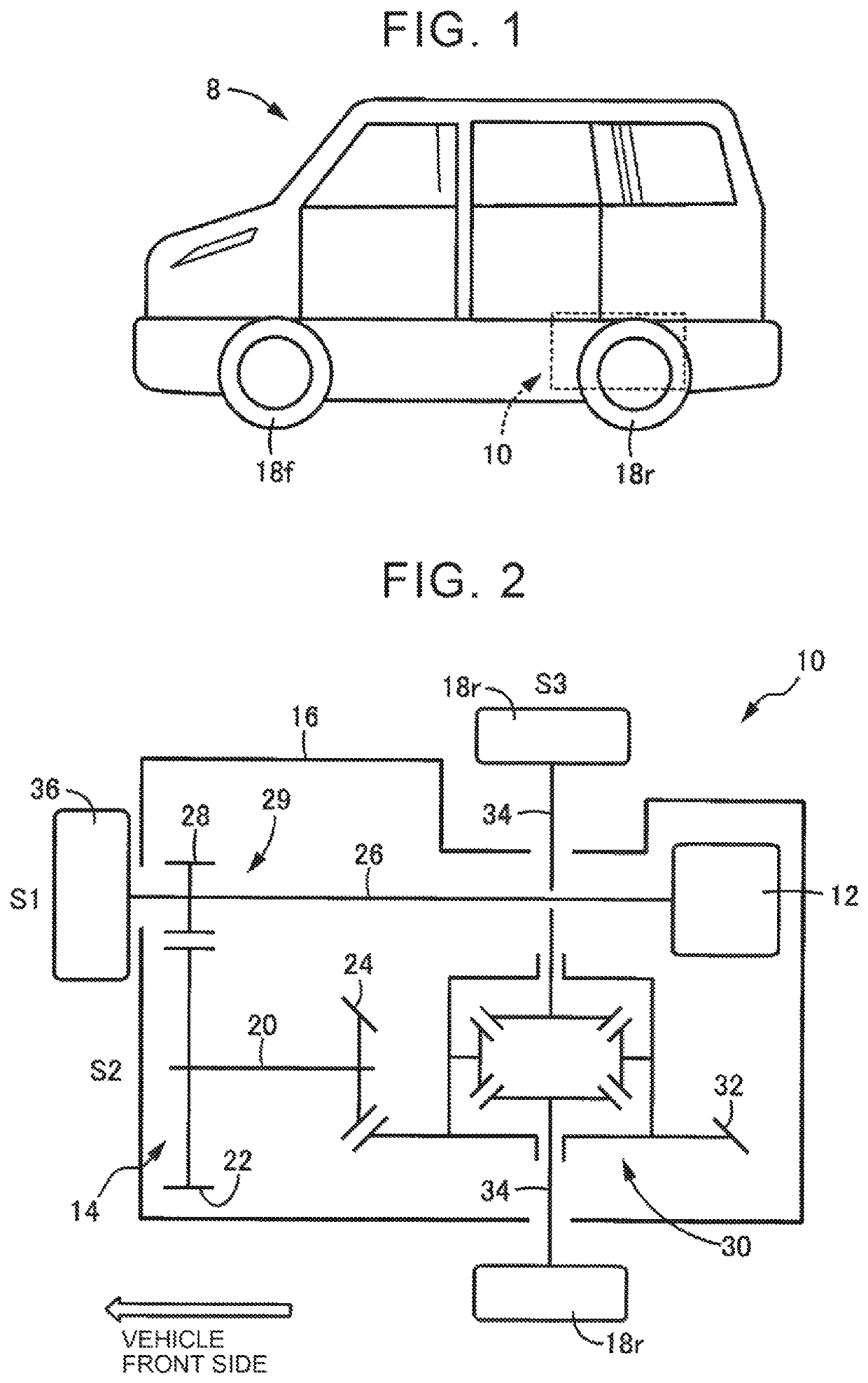
[0041]The disclosure relates to an electric drive device for a vehicle, which includes at least a rotating machine functioning as an electric motor so as to be used as a driving force source for traveling. The disclosure may be applied to an electric vehicle that travels only with the rotating machine. However, the disclosure may also be applied to, for example, a series hybrid vehicle including an engine (internal combustion engine) dedicated to power generation, a parallel hybrid vehicle including an engine as a driving force source, and the like. The electric vehicle may be one that travels using only an in-vehicle battery as a power source, but may be one on which a power generation device such as a fuel cell is mounted. As the rotating machine used as a driving force source, a motor generator may be used that can selectively be used as an electric motor and a generator.

[0042]The disclosure may be applied to a rear-wheel drive vehicle with a driving force source disposed in a re...


PUM


Abstract

An electric drive device for a vehicle includes: a rotating machine that is used as a driving force source for traveling of the vehicle; a differential device configured to distribute power transmitted from the rotating machine to right and left driving wheels; and a retarder provided in a power transmission path between the rotating machine and the differential device and configured to generate a braking force. The retarder is either an electromagnetic retarder or a fluid retarder. The rotating machine and the retarder are arranged on opposite sides of an axis of the differential device in a front-rear direction of the vehicle in a plan view seen from above the vehicle, the axis of the differential device being parallel to a width direction of the vehicle.

Description

INCORPORATION BY REFERENCE[0001]The disclosure of Japanese Patent Application No. 2018-232981 filed on Dec. 12, 2018 including the specification, drawings and abstract is incorporated herein by reference in its entirety.BACKGROUND1. Technical Field[0002]The disclosure relates to an electric drive device for a vehicle, and in particular to an electric drive device for a vehicle, in which a retarder is provided in a power transmission path.2. Description of Related Art[0003]There is a known electric drive device for a vehicle including a rotating machine used as a driving force source for traveling, a differential device that distributes power transmitted from the rotating machine to right and left driving wheels, and an electromagnetic or fluid retarder that is provided in a power transmission path between the rotating machine and the differential device and generates a braking force (see Japanese Unexamined Patent Application Publication No. 2018-23212 (JP 2018-23212 A)).SUMMARY[000...

Claims


Application Information

Patent Timeline
Patent Type & Authority Patents(United States)
IPC IPC(8): B60T13/58B60L7/24B60T1/087B60K1/00
CPCB60T13/586B60L7/24B60T1/087B60K2001/001B60L7/28B60K17/16B60K17/12B60T13/588B60T1/10F16D61/00B60T2270/604F16D63/002
Inventor KUROSAKI, SHIN
Owner TOYOTA JIDOSHA KK
Why Eureka
Try Eureka