
Optical inspection system

an inspection system and optical technology, applied in the field of optical inspection systems, can solve the problems of increasing the overall volume of the system, reducing the utilization efficiency of space, increasing the distance and time, etc., and achieve the effect of reducing the distance and time of the movement of the device under tes

Active Publication Date: 2022-05-31
MPI CORP
View PDF6 Cites 0 Cited by
  • Summary
  • Abstract
  • Description
  • Claims
  • Application Information

AI Technical Summary

Benefits of technology

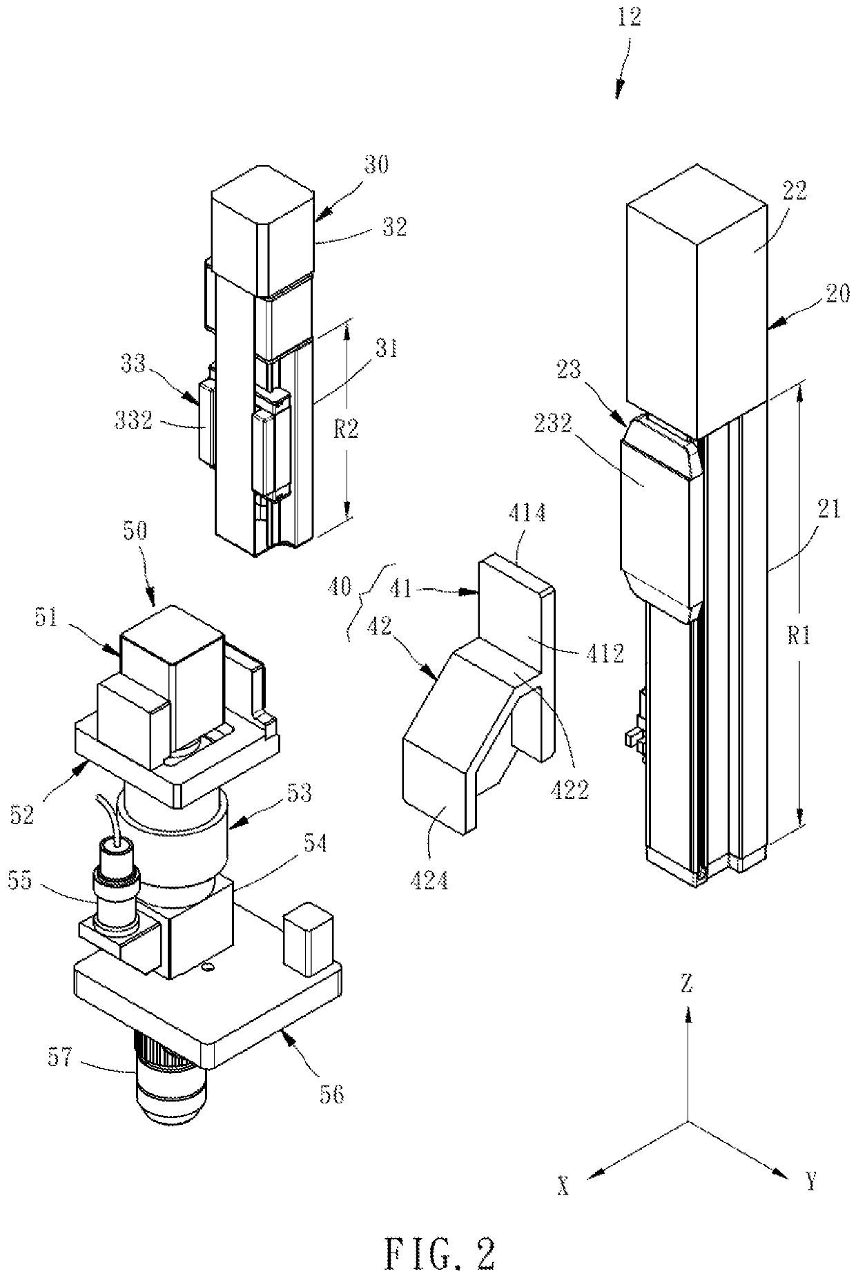
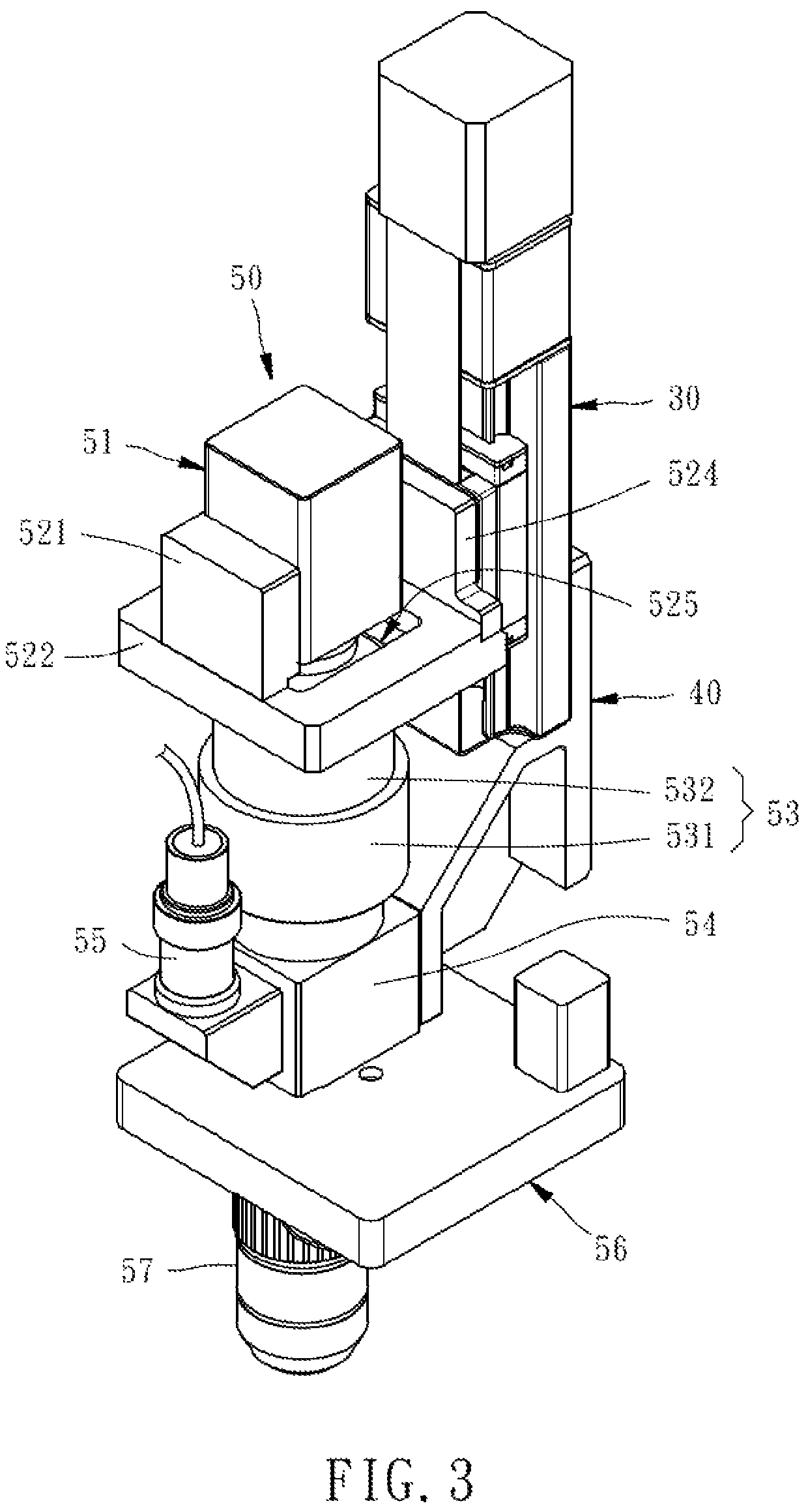
The present invention relates to an optical inspection system that can perform the optical inspection for beam quality factor (M2), space-saving, and reducing the distance and time of the movement of the device under test. The system integrates the near field optical inspection and the beam quality factor (M2) optical inspection in a single module, making it possible to inspect the light emitting element in the same inspecting station successively and saving space. The system has a first displacement device that can move an optical inspection device linearly along an imaginary adjustment axis and a second displacement device that can move the image capturing unit linearly along the same axis. This allows for both near field optical inspection and beam quality factor (M2) optical inspection to be performed using the same inspection module and adjusting the image capturing unit to achieve both a large range and small range of movement.

Problems solved by technology

If an M2 inspecting station is directly added to the original optical inspection system, even though it can achieve the inspecting purpose, it will increase the overall volume of the system, reduce the space utilizing efficiency, and increase the distance and time, for which the device under test should be moved between the inspecting stations.

Method used


Image

  • Optical inspection system
  • Optical inspection system
  • Optical inspection system

Examples


Embodiment Construction

[0015]First of all, it is to be mentioned that same or similar reference numerals used in the following embodiments and the appendix drawings designate same or similar elements or the structural features thereof throughout the specification for the purpose of concise illustration of the present invention. It should be noticed that for the convenience of illustration, the components and the structure shown in the figures are not drawn according to the real scale and amount, and the features mentioned in each embodiment can be applied in the other embodiments if the application is possible in practice. Besides, when it is mentioned that an element is disposed on another element, it means that the former element is directly disposed on the latter element, or the former element is indirectly disposed on the latter element through one or more other elements between aforesaid former and latter elements. When it is mentioned that an element is directly disposed on another element, it means...


PUM

PropertyMeasurementUnit
opticalaaaaaaaaaa
brightness inspectionaaaaaaaaaa
brightnessaaaaaaaaaa

Abstract

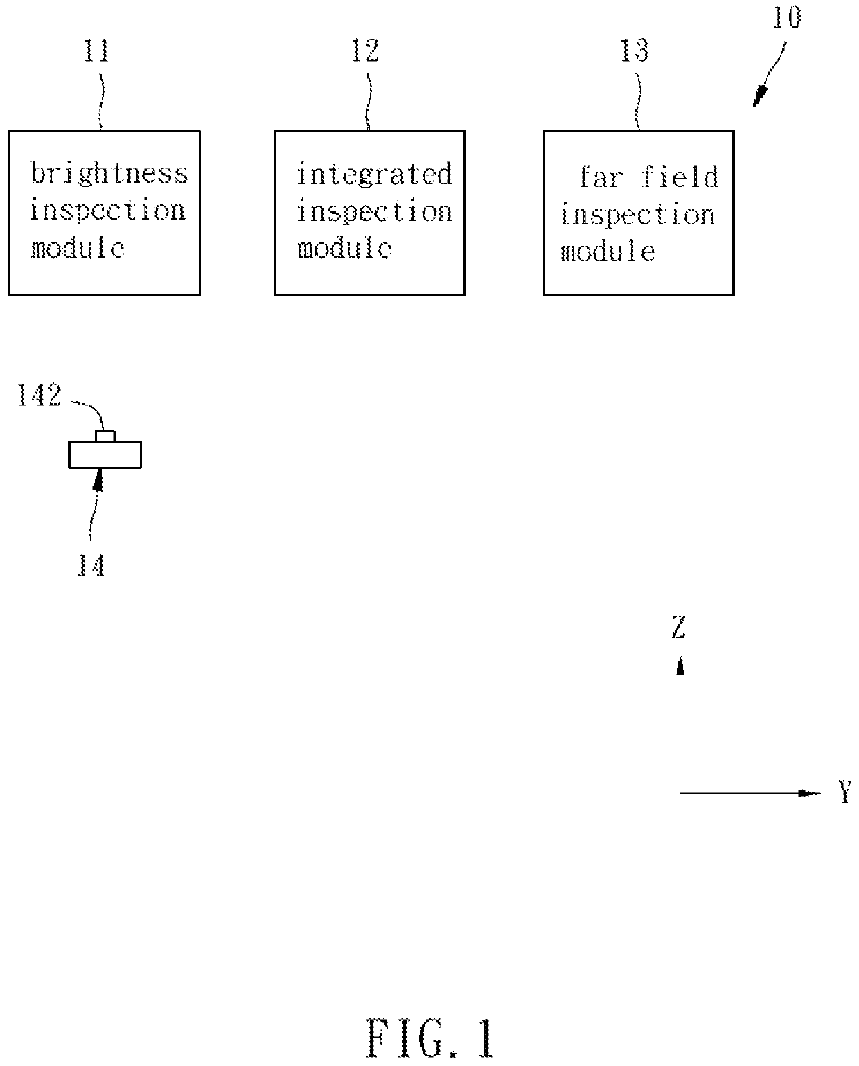
An optical inspection system includes a brightness inspection module for inspecting the brightness of a light emitting element, an integrated inspection module for inspecting the near field optical characteristic and the beam quality factor of the light emitting element, and a far field inspection module for inspecting the far field optical characteristic of the light emitting element. As a result, the optical inspection system is space-saving and capable of reducing the distance and time of the movement of the device under test.

Description

CROSS REFERENCE TO RELATED APPLICATIONS[0001]This non-provisional application claims the benefit under 35 U.S.C. § 119(e) to U.S. Provisional Application No. 62 / 948,186, filed on Dec. 13, 2019, and under 35 U.S.C. § 119(a) to Patent Application No. 109133671, filed in Taiwan on Sep. 28, 2020, all of which are hereby expressly incorporated by reference into the present application.BACKGROUND OF THE INVENTION1. Field of the Invention[0002]The present invention relates generally to inspection systems for inspecting electronic components and more particularly, to an optical inspection system for inspecting a light emitting element.2. Description of the Related Art[0003]The traditional optical inspection system is primarily adapted to inspect the brightness of a device under test by an optical integrating sphere. However, for some specific devices under test, such as vertical-cavity surface-emitting laser array chip (also referred to as ‘VCSEL chip’ hereinafter), an M-Square (M2; also re...

Claims


Application Information

Patent Timeline
Patent Type & Authority Patents(United States)
IPC IPC(8): G01N21/88
CPCG01N21/8806G01N21/8851G01N2021/8887G01J1/4257G01J1/4228G01J2001/4247G01J1/0271G01J1/0448G01J1/0223
Inventor WU, PING-YINGCHEN, CHIU-WANGLIU, YUNG-CHIN
Owner MPI CORP
Learn More