Advanced fiber rope boom pendant technologies for heavy equipment

a technology of fiber rope and boom pendant, which is applied in the direction of textile cables, belts/chains/gears, constructions, etc., can solve the problems of difficult to predict violent motions, large power shovels, and the tendency of superposition principles to produce violent motions in some instances, so as to improve the abrasion resistance and cut resistance

Active Publication Date: 2022-06-07
BRIGHT TECH CO LTD
View PDF14 Cites 0 Cited by
  • Summary
  • Abstract
  • Description
  • Claims
  • Application Information

AI Technical Summary

Benefits of technology

[0022]The present invention comprises a method and hardware for damping and controlling unwanted motion in the fixed rigging of large machines. In a first approach large clamp blocks are added to multi-cable rigging systems. These blocks use a first cable to damp the motion of an adjacent cable. The invention also encompasses adding armored sections to synthetic cables to enhance their abrasion resistance and cut resistance.

Problems solved by technology

Principles of superposition can produce violent motion in some instances.
These violent motions are difficult to predict.
While smaller than the largest dragline cranes, a power shovel is still quite large.
As for the dragline crane, the fixed rigging on the power shovel is not really fixed.
There are some problems unique to power shovels.
Another problem known for power shovels is the fact that the dipper arms can sometimes lift the boom.
The result is a tremendous shock load.
This shock load produces extreme cyclic motion in the stays.
The motion will dampen over time but damage is possible in the interim.
Wire rope is quite tough.
The filaments are very strong in tension, but they are not very rigid and they are not very tough.

Method used


Image

  • Advanced fiber rope boom pendant technologies for heavy equipment
  • Advanced fiber rope boom pendant technologies for heavy equipment
  • Advanced fiber rope boom pendant technologies for heavy equipment

Examples


Embodiment Construction

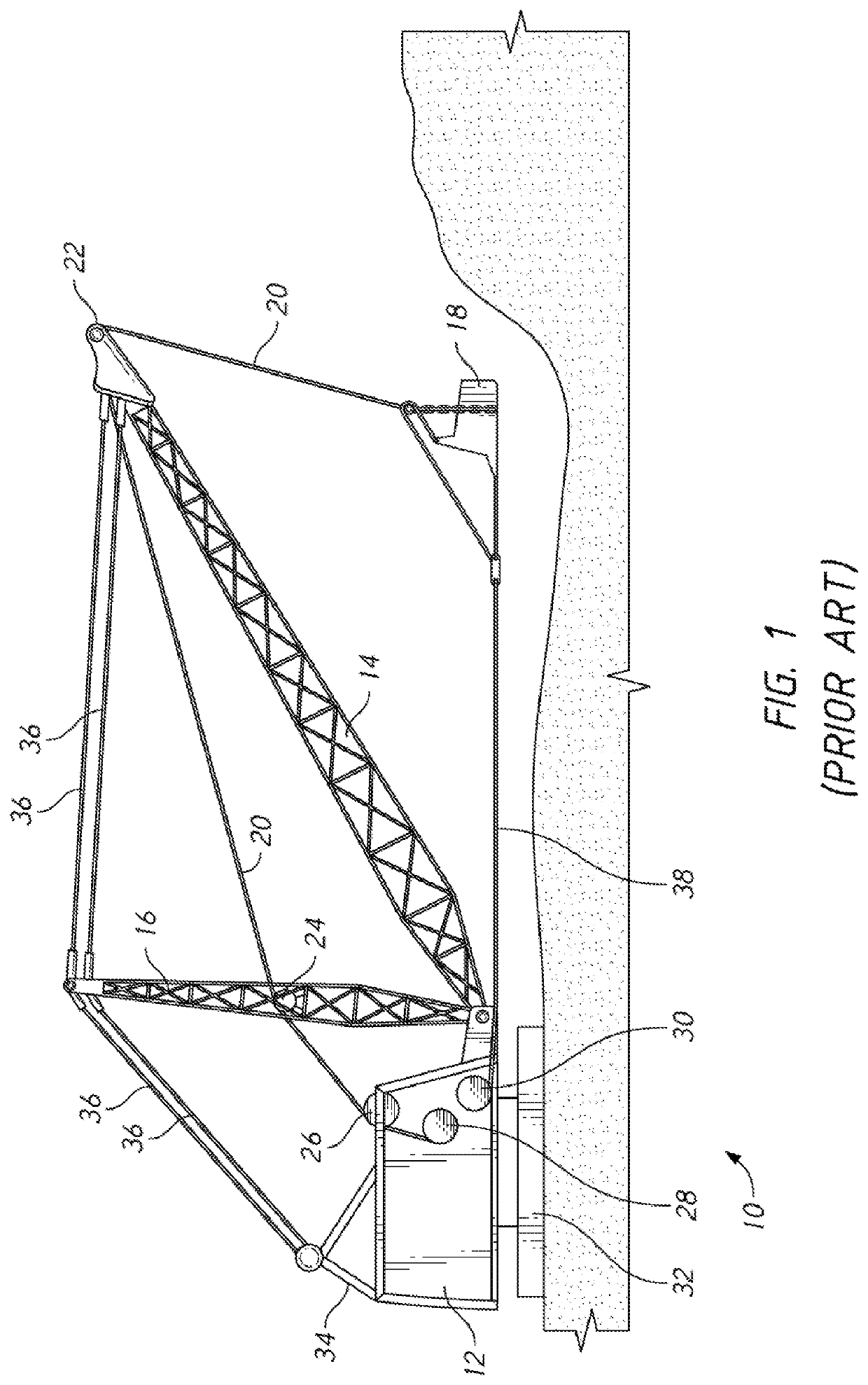
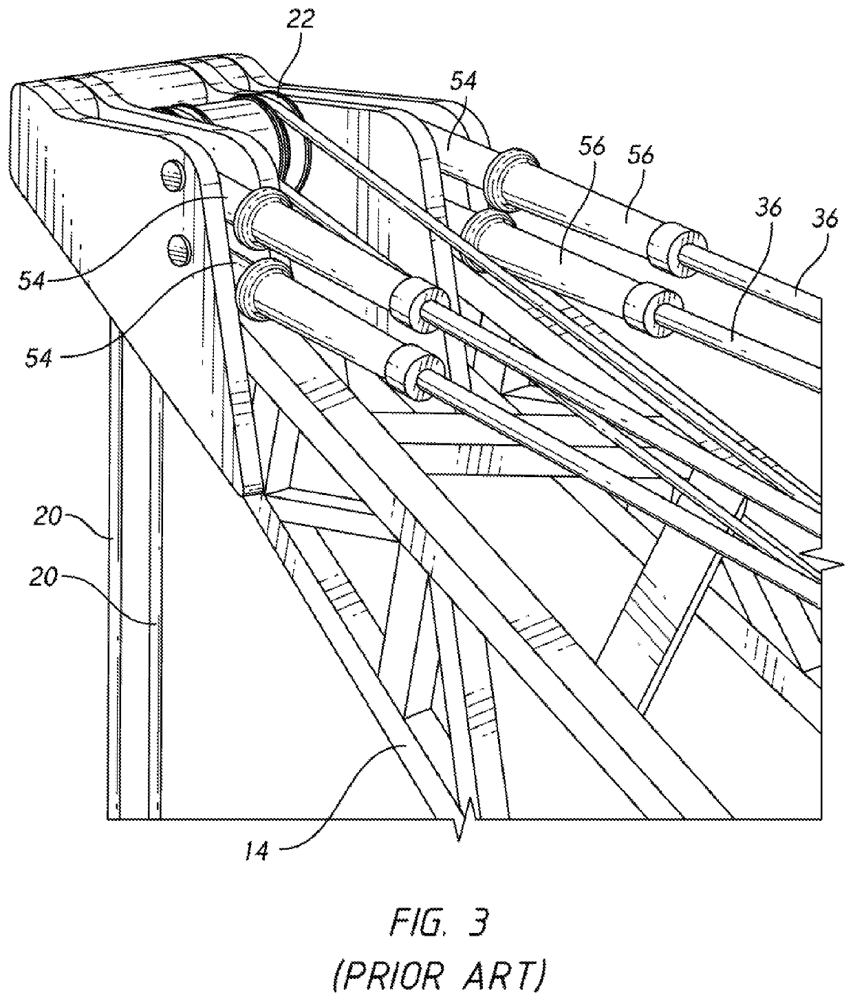
[0085]FIG. 3 shows a detailed view of a particular area of the prior dragline crane shown in FIG. 1. The view centers on the area of point sheave 22—located near the very tip of boom 14. In this example four separate bridge support ropes 36 carry the weight of the boom and the loads imposed by hoist ropes 20 (which raise and lower the bucket). The term “rope” is a traditional term used within the heavy equipment industry. In this context the term rope is a synonym fir a cable or any other term referring to a tensile strength member.

[0086]Each bridge support rope is made primarily (if not fully) from high-strength synthetic filaments. Each of the four bridge support ropes ends in a termination 54. Each termination in this example is connected to the boom by a large transverse pin. Bend restrictors 56 provide a transition between the freely flexing portion of the rope and the portion that is rigidly locked within the termination. In this example, each bend restrictor 56 is approximate...


PUM


Abstract

A method and hardware for damping and controlling unwanted motion in the fixed rigging of large machines. In a first approach large clamp blocks are added to multi-cable rigging systems. These blocks use a first cable to damp the motion of an adjacent cable. The invention also encompasses adding armored sections to synthetic cables to enhance their abrasion resistance and cut resistance.

Description

CROSS-REFERENCES TO RELATED APPLICATIONS[0001]This non-provisional patent application claims the benefit of an earlier-filed provisional patent application. The provisional application was assigned Ser. No. 62 / 640,242. It listed the same inventor.STATEMENT REGARDING FEDERALLY SPONSORED RESEARCH OR DEVELOPMENT[0002]Not Applicable.MICROFICHE APPENDIX[0003]Not ApplicableBACKGROUND OF THE INVENTION1. Field of the Invention[0004]This invention relates to the field of tensile strength members used in the field of heavy lifting and digging equipment.2. Description of the Related Art[0005]The present invention is particularly suited to heavy lifting and digging equipment. It will benefit the reader's understanding to consider some exemplary machines in this field. FIG. 1 shows a prior art dragline crane 10. Cab 12 is mounted on walking shoes 32 that slowly move the machine from one location to the next. A turntable is provided so that the cab can swivel.[0006]Boom 14 is pivotally mounted to...

Claims


Application Information

Patent Timeline
Patent Type & Authority Patents(United States)
IPC IPC(8): E02F3/48E02F3/58E02F3/60E02F9/14
CPCE02F9/14E02F3/58F16G11/042F16G11/025
Inventor CAMPBELL, RICHARD V.
Owner BRIGHT TECH CO LTD
Why Eureka
Try Eureka