Actuators and external controllers therefor

Active Publication Date: 2022-08-16
POWER ENG & MFG
View PDF11 Cites 0 Cited by
  • Summary
  • Abstract
  • Description
  • Claims
  • Application Information

AI Technical Summary

Benefits of technology

[0012]The present invention provides an actuator apparatus and methods which are practical, reliable, accurate, and efficient, and which are believed to fulfill a need and to constitute an improvement over the background technology.
[0014]In contrast to the one hand held box (controller and housing) with one RF module dedicated to control one or more actuators, the present invention involves constructing each actuator with its own unique RF control system and controller pairing protocol. This allows one standard hand held controller with multiple control buttons to control one or more actuators, and to make pairing of controller to actuator easy and reliable. If control of a second or further actuator is needed or desired, a large update is not needed. The user simply adds the actuator, pairs the new actuator to the hand held controller and the system is ready to use.
[0015]Another aspect of the invention involves pairing accuracy. Communication between hand held controller and actuator normally takes place via sub Ghz. RF. Sub Ghz RF permits longer range communication. However, if a hand held controller is addressed to an actuator using such sub Ghz RF transmission, the possibility exists of pairing of the controller with an intended actuator that is located a long distance away, for example approximately 50 feet or more away, and not the actuator (typically closer to the user) that the user intended to pair with. The present invention therefore adds Ghz RF transmission means, which is used during pairing so that the user can limit and control can better limit the distance locally for pairing accuracy.
[0016]A further aspect of the invention involves increase reliability and safety of operation. In many work environments in which remote controllable actuators are used, the use of microprocessors with firmware is considered a high risk. A single point processor failure can cause unintended motion and possibly an unintended and unsafe operation. The present invention therefore utilizes a second processor in a specific mode of operation to oversee and enable operation. Thus two (2) processor failures would be required to permit an unintended operation.
[0029]In contrast to the one hand held box (controller and housing) with one RF module dedicated to control one or more actuators, the present invention involves constructing each actuator with its own unique RF control system and controller pairing protocol. This allows one standard hand held controller with multiple control buttons to control one or more actuators, and to make pairing of controller to actuator easy and reliable. If control of a second or further actuator is needed or desired, a large update is not needed. The user simply adds the actuator, pairs the new actuator to the hand held controller and the system is ready to use.
[0030]Another aspect of the invention involves pairing accuracy. Communication between hand held controller and actuator normally takes place via sub GHz. RF. Sub GHz RF permits longer range communication. However, if a hand held controller is addressed to an actuator using such sub Ghz RF transmission, the possibility exists of pairing of the controller with an intended actuator that is located a long distance away, for example approximately 50 feet or more away, and not the actuator (typically closer to the user) that the user intended to pair with. The present invention therefore adds Ghz RF transmission means, which is used during pairing so that the user can limit and control can better limit the distance locally for pairing accuracy.

Problems solved by technology

However, if a hand held controller is addressed to an actuator using such sub Ghz RF transmission, the possibility exists of pairing of the controller with an intended actuator that is located a long distance away, for example approximately 50 feet or more away, and not the actuator (typically closer to the user) that the user intended to pair with.

Method used


Image

  • Actuators and external controllers therefor
  • Actuators and external controllers therefor
  • Actuators and external controllers therefor

Examples


first embodiment

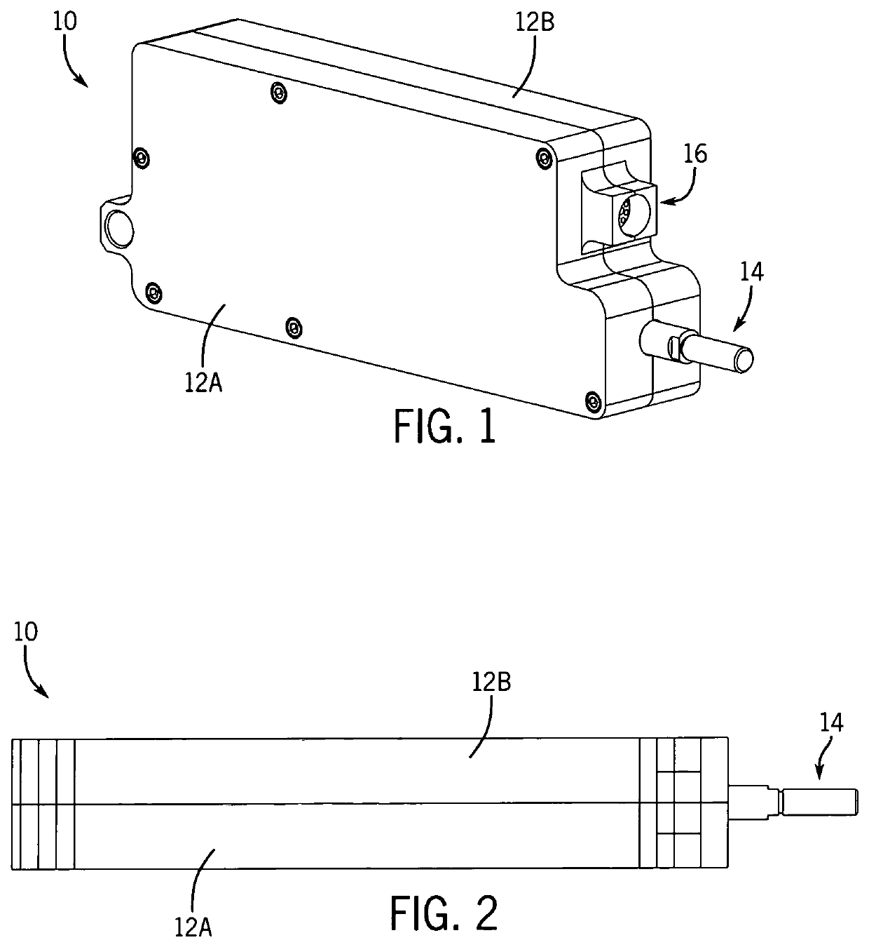
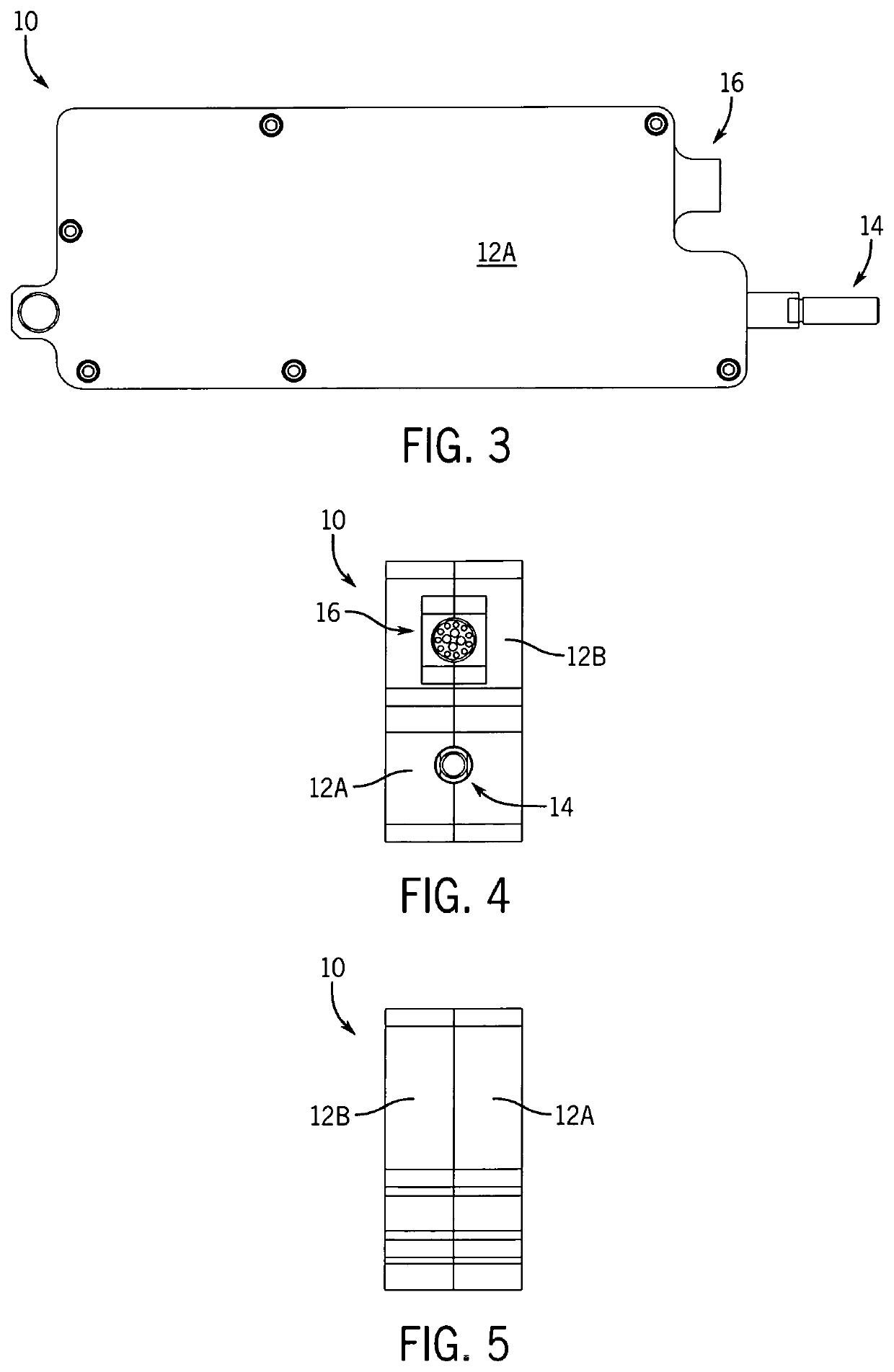
[0091]FIGS. 1-5 show the exterior of an actuator 10 of the invention. The actuator 10 is compact, efficient, accurate, and reliable. The actuator 10 has a substantially rectilinear housing 12 that protects and serves as a base for various internal mechanical and electrical components. At one end, a mechanical output rod 14 exits the housing 12 at an aperture there though. A port 16 is shown disposed at the same end as the output rod 14, and provides power to the actuator 10 and in some embodiments may provide control connections. Although the rod 14 is shown to have a curvilinear configuration, it is within the purview of the invention that it may have a rectilinear or other configuration or geometry. Similarly, the power and control port 16 may have various other configurations. As will be described further below, this embodiment of the invention includes, but is not limited to, idler gears, a rotary position sensor, and plural processors.

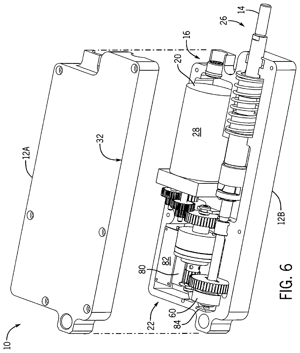
[0092]Turning to FIGS. 6 and 7, the actuato...

second embodiment

[0106]FIGS. 28-32 show the exterior of an actuator 210 of the invention. The actuator 210 is also efficient and reliable. The actuator 210 has a substantially rectilinear housing 216 that protects and serves as a base for various internal mechanical and electrical components. At a first or distal end 214, a mechanical output rod 236 exits the housing 216 at an aperture there though. A sealed power and control port or connector 248 is shown disposed at the opposite, proximal end 212 of the actuator 210, and provides power to the actuator 210 and in some embodiments may provide control connections. Although the rod 236 is shown to have a curvilinear configuration, it is within the purview of the invention that it may have a rectilinear or other configuration or geometry. Similarly, the power and control port 248 may have various other configurations. As is described further below, this embodiment of the invention includes in-line planetary gears, a linear position sensor, and a single...


PUM


Abstract

An actuator for use with an external controller, either alone or in a group including other actuators controlled from the same external controller. The actuator includes a housing for encasing internal components of the device; a motor assembly for creating motion, the motor assembly being disposed within the housing; and a drive assembly for driving a pushrod, the drive assembly being arranged within the housing and slidingly connected to the motor assembly. A remote control communication circuit is electrically connected to the motor. The actuator includes an in line planetary gear and a linear position sensor. The actuator may include a hand held remote controller which utilizes tilt for proportional control, and a distributed network.

Description

CROSS-REFERENCE TO RELATED APPLICATIONS, IF ANY[0001]This application is a continuation-in-part of U.S. patent application Ser. No. 16 / 429,942, filed 3 Jun. 2019, status pending, which is hereby incorporated by reference.37 C.F.R. § 1.71 (e) AUTHORIZATION[0002]A portion of the disclosure of this patent document contains material which is subject to copyright protection. The copyright owner has no objection to the facsimile reproduction by anyone of the patent document or the patent disclosure, as it appears in the US Patent and Trademark Office patent file or records, but otherwise reserves all copyright rights whatsoever.STATEMENT REGARDING FEDERALLY SPONSORED RESEARCH OR DEVELOPMENT[0003]Not applicable.REFERENCE TO A MICROFICHE APPENDIX, IF ANY[0004]Not applicable.BACKGROUND1. Field of the Invention[0005]The present invention relates, generally, to electro-mechanical technology. More particularly, the invention relates to electro-mechanical actuator systems, apparatus, and methods...

Claims


Application Information

Patent Timeline
Patent Type & Authority Patents(United States)
IPC IPC(8): F16H25/20G08C17/02G01D5/14H02K7/116H02K7/108H02K11/21
CPCF16H25/20G01D5/14G08C17/02H02K7/108H02K7/116H02K11/21F16H2025/2031F16H2025/2071F16H2025/2081F16H2025/2087F16H25/2015H02K11/215H02K11/35G08C2201/20G01D5/16F16H2025/2075
Inventor BLESENER, JAMES LAWRENCEAMIGHI, AMIR HOOSHANG
Owner POWER ENG & MFG
Why Eureka
Try Eureka