Timepiece comprising a mechanical oscillator associated with a regulation system

a mechanical oscillator and timepiece technology, applied in the field of timepieces, can solve the problems of only functional electronic regulation, timepiece parasitic loss, and error in voluntary isochronism

Active Publication Date: 2022-08-23
THE SWATCH GRP RES & DEVELONMENT LTD
View PDF7 Cites 2 Cited by
  • Summary
  • Abstract
  • Description
  • Claims
  • Application Information

AI Technical Summary

Benefits of technology

[0013]The first aim of the present invention is that providing a timepiece of the type described above and which is capable of correcting a loss or a gain in the time drift of the mechanical oscillator while making it possible to carry out self-powering of the regulation system effectively.
[0016]A further aim is that of using the electrical regulation energy to power an auxiliary function and therefore an auxiliary load, by storing this electrical energy effectively without giving rise to instability in the functioning of the regulating device or disturbance of regulation.
[0030]Transferring a first electric load in a first time zone as defined is envisaged to increase the recharging of the power supply capacitor upon the appearance of a first voltage lobe following this transfer, relative to the scenario where no transfer would take place. This increase in recharging means greater mechanical energy drawn from the mechanical oscillator by the braking system and therefore superior braking of this mechanical oscillator. As described hereinafter, braking in a first half-alternation before the passage of the mechanical resonator via the neutral position thereof induces a negative time-lag in the oscillation of the resonator, and thus the duration of the alternation in question is increased. Therefore, the instantaneous frequency of the mechanical oscillator is momentarily reduced and this results in a certain loss in the running of the mechanism which corrects at least partially the gain detected by the measuring device. Similarly, transferring a second electric load in a second time zone as defined is envisaged to increase the recharging of the power supply capacitor upon the appearance of a second voltage lobe following this extraction, relative to the scenario where no extraction would take place. As shall be understood hereinafter, this induces a positive time-lag in the oscillation of the resonator, and thus the duration of the alternation in question is reduced. Therefore, the instantaneous frequency of the mechanical oscillator is momentarily increased and this results in a certain gain in the running of the mechanism which corrects at least partially the loss detected by the measuring device.

Problems solved by technology

Thus, in the case of the mechanical oscillator, those skilled in the art understand that regulation is only possible when the barrel spring is strongly armed and that the free oscillation frequency (natural frequency) of the mechanical oscillator is greater than the reference frequency FR, resulting from a voluntary isochronism error of the selected mechanical oscillator.
Therefore, there is a two-fold problem, i.e. the mechanical oscillator is selected for that which is usually an error in a mechanical movement and the electronic regulation is only functional when the natural frequency of this oscillator is greater than a nominal frequency.
One may have strong doubts that this is achieved with the electromagnetic assembly disclosed and a conventional rectifier connected to a storage capacitor.
Thus, a braking results therefrom which is not symmetrical relative to the neutral position and a parasitic loss in the running of the timepiece.

Method used


Image

  • Timepiece comprising a mechanical oscillator associated with a regulation system
  • Timepiece comprising a mechanical oscillator associated with a regulation system
  • Timepiece comprising a mechanical oscillator associated with a regulation system

Examples


first embodiment

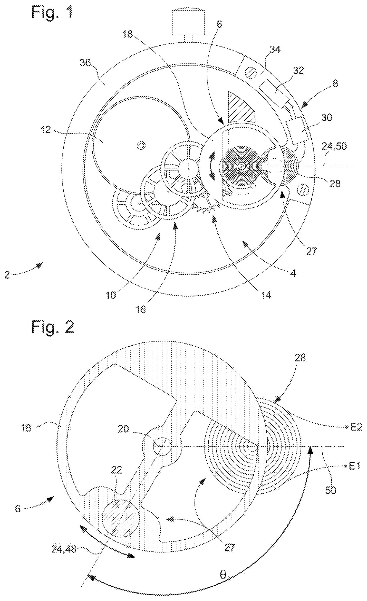
[0071]With reference to FIGS. 1 and 2 described above and to FIGS. 7 to 10C, a timepiece according to the invention shall be described hereinafter. This timepiece 2 comprises:[0072]a mechanism 12, 16 (shown partially),[0073]a mechanical resonator 6 (balance-spring) suitable for oscillating about a neutral position 48 corresponding to the minimal mechanical potential energy state thereof, each alternation of the successive oscillations having a passage of the mechanical resonator via the neutral position thereof at a median time and consisting of a first half-alternation ending at the median time thereof and of a second half-alternation starting at the median time thereof,[0074]a maintenance device 14 of the mechanical resonator forming with this mechanical resonator a mechanical oscillator which sets the running speed of the mechanism,[0075]an electromechanical transducer arranged to be able to convert mechanical power from the mechanical oscillator into electrical power, when the m...

second embodiment

[0093]With the aid of FIGS. 11 to 15, a timepiece according to the invention shall be described hereinafter.

[0094]FIG. 11 is similar to FIG. 2, but for an electromagnetic assembly 29 forming the electromagnetic transducer of a timepiece according to the second embodiment. It shows the mechanical resonator 6a in a horizontal cross-section at the level of the balance 18a thereof, this mechanical resonator being incorporated in a timepiece movement, similar to that in FIG. 1, instead of the resonator 6 shown in this FIG. 1. The references previously described shall not be described again herein. As a general rule, there is envisaged an electromagnetic assembly which comprises at least the coil 28 and a magnetized structure formed from at least one magnet and having at least one pair of magnetic poles, of opposite polarities, each generating a magnetic flux in the direction of a general plane of the coil, this pair of magnetic poles being arranged such that, when the mechanical resonato...

third embodiment

[0116]FIG. 19 is a flow chart of the regulation method implemented in the logic control circuit 62b of the All the features, all the electrical signals and the consequences of the various events that occur shall not be described in more detail, as they ensue from the explanations previously given above and the results are readily understood in the light of these explanations.

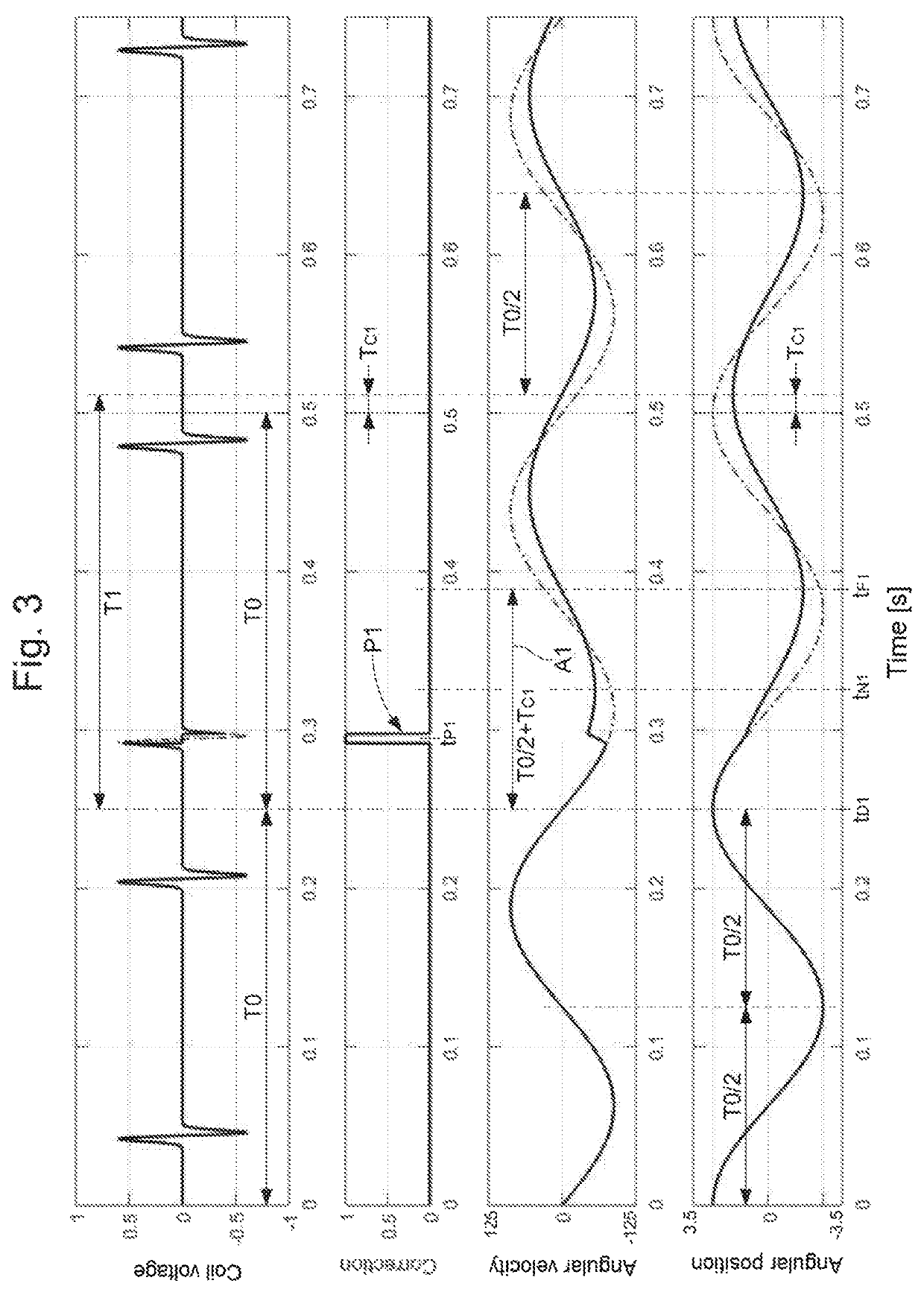
[0117]When the regulation device is started, the regulation circuit 74 is set to ‘POR’, in particular the bidirectional counter CB. The logic circuit then waits for the appearance of a pulse S2, namely in particular the rising edge thereof in the signal ‘Comp’. The detection of this rising edge triggers the timer which measures a first time interval TC2 the duration whereof is chosen such that the end thereof occurs in a first time zone ZT1 situated temporally between a second voltage lobe LUC2 and a first voltage lobe LUC1, particularly between the time t2 and the time t1 where these two lobes exhibit respecti...


PUM


Abstract

A timepiece includes a mechanical movement with a mechanical oscillator and an electronic device for regulating the medium frequency of this mechanical oscillator. It includes an electromagnetic transducer and an electric converter which includes a primary storage unit for powering the regulation circuit. The electromagnetic transducer is arranged to supply a voltage signal exhibiting first voltage lobes in first half-alternations and second voltage lobes in second half-alternations of the oscillations of the mechanical oscillator. The regulating device includes a load pump arranged to transfer electric loads from the primary storage unit into a secondary storage unit, these electric loads being extracted selectively in different time zones according to a time drift detected in the functioning of the mechanical oscillator relative to an auxiliary oscillator, particularly quartz-based.

Description

CROSS-REFERENCE TO RELATED APPLICATION[0001]This application claims priority to European Patent Application No. 17209121.7 filed on Dec. 20, 2017, the entire disclosure of which is hereby incorporated herein by reference.TECHNICAL FIELD[0002]The present invention relates to a timepiece comprising a mechanical oscillator associated with a system for regulating the medium frequency thereof. The regulation is of the electronic type, i.e. the regulation system comprises an electronic circuit connected to an auxiliary oscillator which is arranged to supply a high-precision electric clock signal. The regulation system is arranged to correct a potential time drift of the mechanical oscillator relative to the auxiliary oscillator.[0003]In particular, the mechanical oscillator comprises a mechanical resonator formed by a balance-spring and a maintenance device formed by a conventional escapement, for example having Swiss pallets. The auxiliary oscillator is formed particularly by a quartz re...

Claims


Application Information

Patent Timeline
Patent Type & Authority Patents(United States)
IPC IPC(8): G04C3/06G04G19/06G04C10/00G04B17/06G04C3/04
CPCG04C3/068G04B17/06G04C3/04G04C10/00G04G19/06
Inventor TOMBEZ, LIONEL
Owner THE SWATCH GRP RES & DEVELONMENT LTD
Why Eureka
Try Eureka