Wave-energized buoyant water elevator for raising water in response to tilting about multiple distinct angularly-spaced axes

a buoyant water elevator and wave-energized technology, applied in the direction of mechanical equipment, machines/engines, sea energy generation, etc., can solve problems such as tending to tilt about a vertical axis

Active Publication Date: 2022-09-06
LONE GULL HLDG LTD
View PDF3 Cites 1 Cited by
  • Summary
  • Abstract
  • Description
  • Claims
  • Application Information

AI Technical Summary

Benefits of technology

The patent text describes a mechanism that allows water to flow in a pattern that raises its height and converts its potential energy into electrical power. This mechanism includes a design feature that allows water to bypass a water turbine or other flow restrictor and return to the body of water from which it originated. This bypass provides a useful adaptation to avoid damage during periods of operation characterized by waves of excessive energy.

Problems solved by technology

However, they also tend to tilt about a vertical axis (i.e. to pitch and / or roll).

Method used


Image

  • Wave-energized buoyant water elevator for raising water in response to tilting about multiple distinct angularly-spaced axes
  • Wave-energized buoyant water elevator for raising water in response to tilting about multiple distinct angularly-spaced axes
  • Wave-energized buoyant water elevator for raising water in response to tilting about multiple distinct angularly-spaced axes

Examples


embodiment 650

[0445]FIG. 71 shows a perspective side view of an embodiment 650 of the present disclosure that incorporates a plurality of the type of power takeoff (PTO) disclosed herein. The embodiment floats adjacent to an upper surface 651 of a body of water over which waves tend to pass. Each hexagonal columnar structure, e.g., 652-654, is a PTO of one of the types disclosed herein. The embodiment may incorporate a variety of different PTOs, PTOs of different sizes, PTOs of different rated electrical power levels, PTOs fabricated of different materials, PTOs converting the energy of waves into electrical power by means of different operating fluids, PTOs which draw water from the body of water 651 and PTOs that recycle an operating fluid within a closed system.

[0446]The illustrated multi-PTO embodiment 650 incorporates an energy-consuming processing module 655, system, factory, mechanism, and / or device, and therein or therethrough utilizes at least a portion of the electrical power that it pr...

embodiment 700

[0454]FIG. 72 shows a perspective side view of an embodiment 700 of the present disclosure. A compartment, enclosure, and / or chamber 701, contains a wave-energized diode pump similar to the one illustrated in FIGS. 15-19 which utilizes reservoirs connected to ramps, and / or inclined channels, over and / or through which, in response to wave-induced tilting of the diode pump, water flows back and forth between opposing reservoirs at ever increasing relative heights thereby progressively and / or incrementally gaining gravitational potential energy.

[0455]Water that has flowed through the diode pump and reached the top of the pump is thereafter directed into a channel (not visible) containing a water turbine (not visible) rotatably connected to a generator 702. The water flowing down through the turbine channel engages and / or energizes the water turbine thereby imparting rotational kinetic energy and / or rotational torque to the generator 702 and thereby generating electrical power.

[0456]The...

embodiment 800

[0504]FIG. 87 shows a perspective side view of an embodiment 800 of the present disclosure. The illustrated embodiment is similar to an “autonomous underwater vehicle” (AUV) and is capable of cruising through a body of water below its surface. However, in FIG. 87 the embodiment is shown floating adjacent to an upper surface 801 of a body of water over which waves are passing. The embodiment incorporates, includes, and / or utilizes, four stabilizing and / or directional fins, e.g., 802, at a fore 803, forward, leading, and / or upper end, as well as four stabilizing and / or directional fins, e.g., 804, at an aft 805, stern, trailing, and / or lower end. In combination with a forward or backward thrust, the embodiment's fins, e.g., 802 and 804, enable and / or permit the embodiment to alter, adjust, control, regulate, change, and / or modify, its pitch, yaw, roll, course, direction, and / or movements.

[0505]The illustrated embodiment 800 has a hull, shape, form, and / or displacement, that is primari...


PUM


Abstract

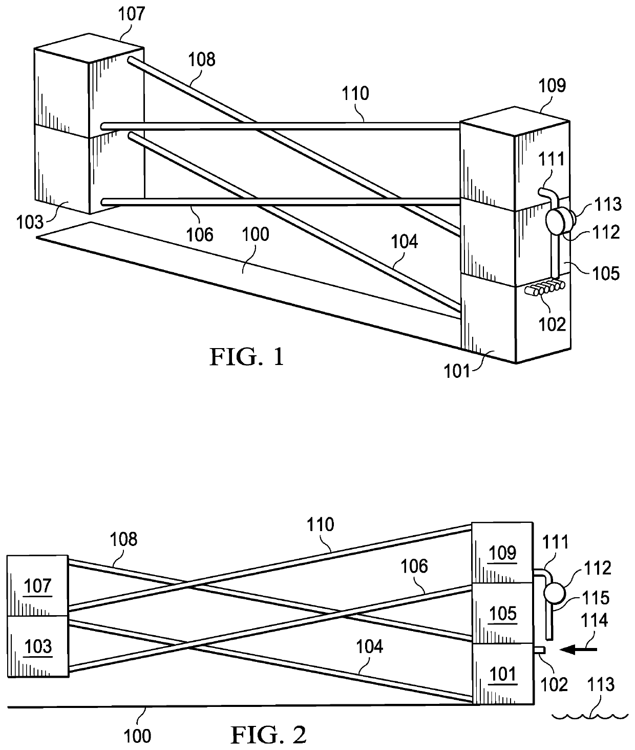
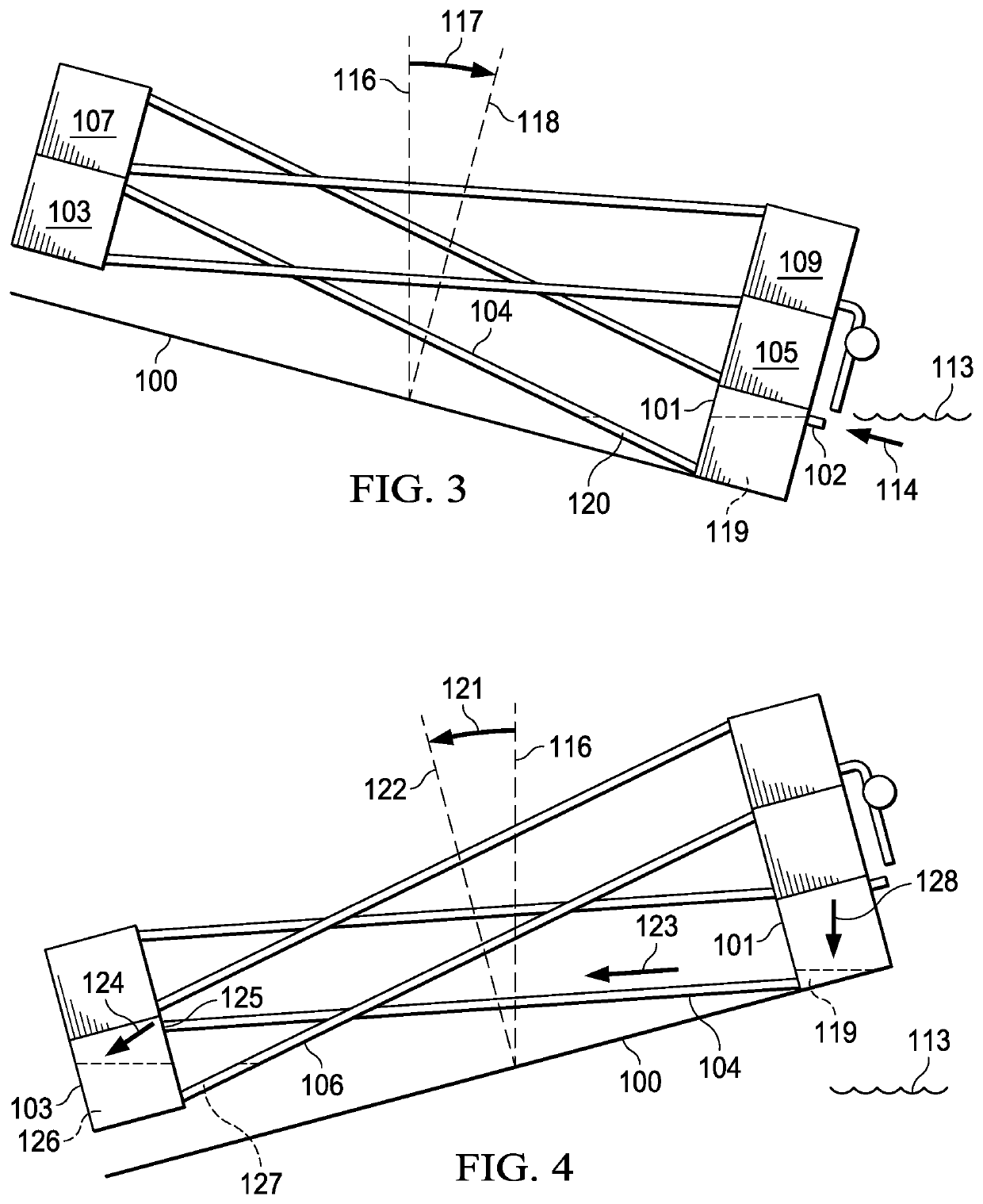
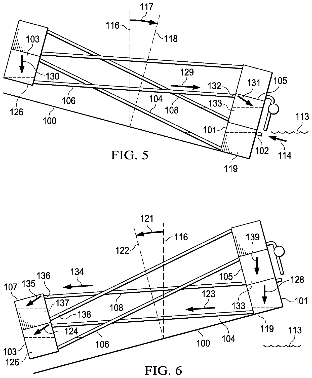
Disclosed is an apparatus that floats at the surface of a body of water over which waves pass. Passing waves cause a nominally vertical axis of the apparatus to tilt away from an axis normal to the resting surface of the body of water. Tilting of sufficient magnitude and duration allows a fluid to flow through a channel that in an un-tilted apparatus would require the gravitational potential energy of the fluid to increase (i.e., to flow uphill), but, because of the tilt allows the fluid to flow through the channel in a downhill direction. Flowing water is trapped at a plurality of levels which in an un-tilted apparatus are higher than the respective levels from which the fluid has flowed. A subsequent tilt of the apparatus in a sufficiently different direction, and of a sufficient magnitude and duration, causes the trapped water to flow to new, yet higher levels. Successive wave-driven tilts of the apparatus incrementally raise water to a height and / or head from which a portion of its gravitational potential energy can be released, and / or converted to electrical power, by causing the water to return to a lower level by flowing through a water turbine thereby energizing an operationally connected generator, or through some other apparatus that performs a useful function when supplied with a flow of high-pressure water.

Description

CROSS-REFERENCES TO RELATED APPLICATIONS[0001]This divisional application is based on U.S. Ser. No. 16 / 796,724, filed on Feb. 20, 2020, which claims priority to U.S. Provisional Patent Application Nos. 62 / 809,566 filed Feb. 23, 2019; 62 / 834,964 filed Apr. 17, 2019 and 62 / 971,963, filed Feb. 8, 2020, the contents of which are incorporated herein by reference in their entirety.BACKGROUND[0002]Extracting energy from ocean waves has proven to be a difficult endeavor. Complex devices are expensive and tend to be fragile. And devices with articulating elements are prone to damage during storms. In fact, devices with moving parts tend to require frequent maintenance and repair and therefore produce power that tends to be prohibitively expensive.[0003]What has been needed is a wave-energy conversion technology, apparatus, and / or technology that is simple, has a minimum number of moving parts, and has no articulating elements. What has been needed is a wave-energy conversion technology, appa...

Claims


Application Information

Patent Timeline
Patent Type & Authority Patents(United States)
IPC IPC(8): F03B13/22F03B13/20
CPCF03B13/20F03B13/22F03B13/144F05B2240/13F05B2240/93Y02E10/30F03B13/145
Inventor MOFFAT, BRIAN LEESHELDON-COULSON, GARTH ALEXANDER
Owner LONE GULL HLDG LTD
Why Eureka
Try Eureka