
Spike pulse generation circuit comprising single silicon device

a technology of silicon devices and pulse generators, applied in pulse generators, pulse techniques, semiconductor/solid-state device details, etc., can solve the problems of inability to continuously expand complementary metal oxide semiconductor (cmos) technology, physical limitations of von neumann computing, and inability to achieve continuous expansion of complementary metal oxide semiconductor technology

Active Publication Date: 2022-09-13
KOREA UNIV RES & BUSINESS FOUND
View PDF4 Cites 0 Cited by
  • Summary
  • Abstract
  • Description
  • Claims
  • Application Information

AI Technical Summary

Benefits of technology

The present patent text describes a spike pulse generation circuit that uses a single silicon device and resistors. This circuit improves processing speed and integration limits, and can perform processing like a human brain. Additionally, the circuit can have two terminals, similar to a biological neuron, and does not require an external power supply or bias input.

Problems solved by technology

Due to the explosion of data generated by Internet of Things in the fourth industry, existing von Neumann computing faces physical limitations with regard to data processing.
In other words, exiting von Neumann-based computers exhibit a high operation speed in sequential mathematical calculations, but exhibit limitations in terms of speed and power consumption in calculating simultaneous inputs and outputs.
In addition, continuous expansion of Complementary Metal Oxide Semiconductor (CMOS) technology is no longer possible.
Existing memory devices cannot operate in parallel in both directions and have difficulty in implementing synaptic plasticity.
However, as performance increases, a bottleneck problem has occurred with regard to data processing speed, which presents a limitation in processing large amounts of data.
Although CMOS-based neuromorphic circuits have been developed for spike-based calculations, the complexity of the circuit and the lack of critical dynamics of biological systems may motivate utilization of new memory device technologies such as phase change memory, resistive memory and ferroelectric memory.
In addition, the need for external bias or power supply for circuit operation may be limited in emulating biological neurons that operate only as input signals.
Existing NDR oscillators using MIT materials cannot utilize an existing CMOS process, and application of CMOS-based ring oscillators to the neuromorphic technology is limited in terms of integration despite excellent performance thereof due to use of a large number of transistors.

Method used


Image

  • Spike pulse generation circuit comprising single silicon device
  • Spike pulse generation circuit comprising single silicon device
  • Spike pulse generation circuit comprising single silicon device

Examples


Embodiment Construction

[0061]The present disclosure will now be described more fully with reference to the accompanying drawings, in which exemplary embodiments of the disclosure are shown.

[0062]This disclosure, however, should not be construed as limited to the exemplary embodiments and terms used in the exemplary embodiments, and should be understood as including various modifications, equivalents, and substituents of the exemplary embodiments.

[0063]Preferred embodiments of the present disclosure are now described more fully with reference to the accompanying drawings. In the description of embodiments of the present disclosure, certain detailed explanations of related known functions or constructions are omitted when it is deemed that they may unnecessarily obscure the essence of the disclosure.

[0064]In addition, the terms used in the specification are defined in consideration of functions used in the present disclosure, and can be changed according to the intent or conventionally used methods of clien...


PUM


Abstract

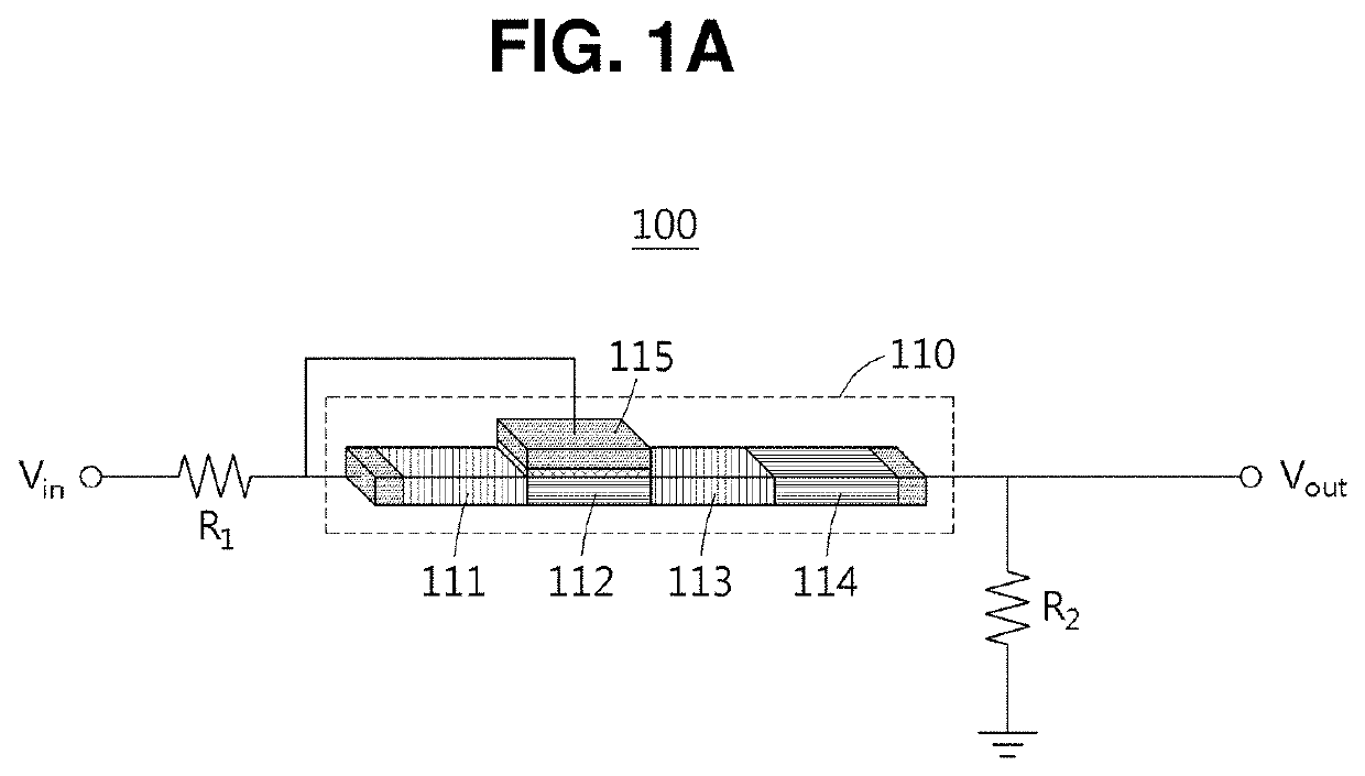
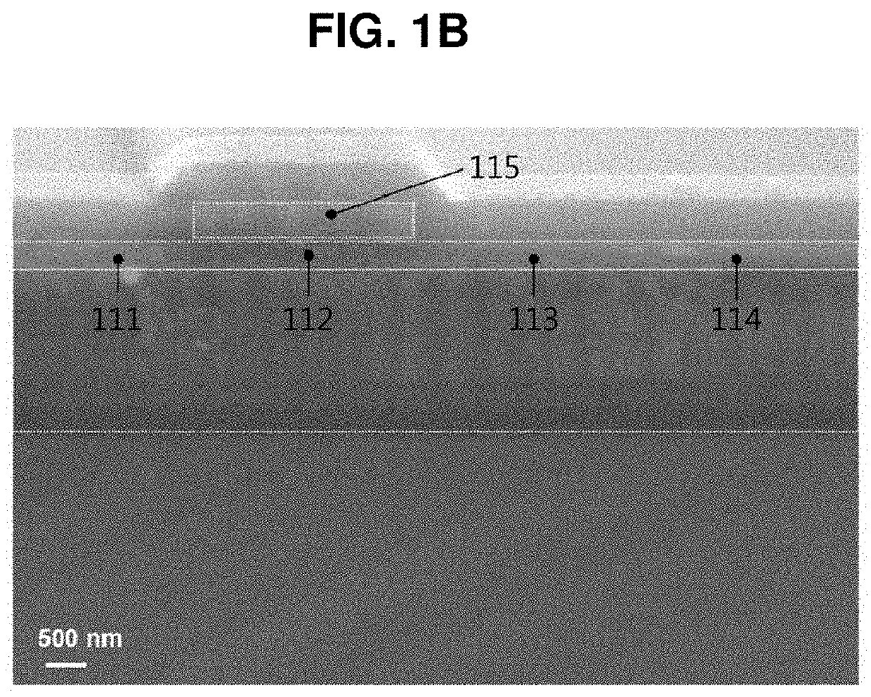
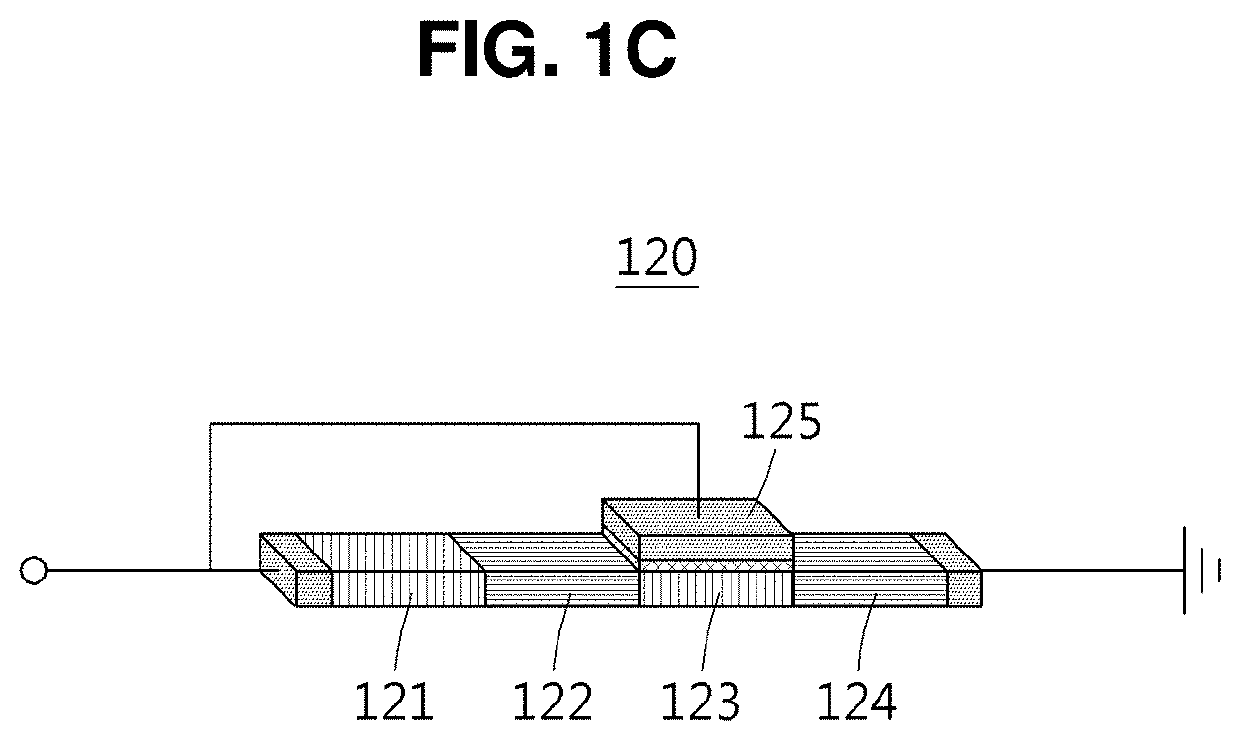
Provided is a spike pulse generation circuit comprising a single silicon device configured to non-periodically or periodically generate a spike pulse. More particularly, the spike pulse generation circuit comprising the single silicon device can utilize a positive feedback loop and a negative feedback loop to be mutually connected so as to selectively output a spike pulse related to a neural oscillation function similar to biological oscillation, thereby being capable of serving as a ring oscillator and performing a neuron function operation.

Description

CROSS-REFERENCE TO RELATED APPLICATION[0001]This application claims priority to Korean Patent Application No. 10-2020-0081116, filed on Jul. 1, 2020 in the Korean Intellectual Property Office, the disclosure of which is incorporated herein by reference.BACKGROUND OF THE DISCLOSUREField of the DisclosureThe Present Disclosure[0002]The present disclosure relates to a spike pulse generation circuit comprising a single silicon device configured to non-periodically or periodically generate a spike pulse, and more particularly to a spike pulse generation circuit comprising a single silicon device configured to utilize a positive feedback loop and a negative feedback loop to be mutually connected so as to selectively output a spike pulse related to a neural oscillation function similar to biological oscillation, thereby being capable of serving as a ring oscillator and performing a neuron function operation.Description of the Related Art[0003]Due to the explosion of data generated by Inter...

Claims


Application Information

Patent Timeline
Patent Type & Authority Patents(United States)
IPC IPC(8): H03K3/03H01L23/00
CPCH03K3/0315H01L23/00G06N3/063B82Y10/00H01L29/74H01L29/7391H01L29/423
Inventor KIM, SANG SIGCHO, KYOUNG AHLIM, DOO HYEOK
Owner KOREA UNIV RES & BUSINESS FOUND
Learn More