Supercharge Your Innovation With Domain-Expert AI Agents!

Wireless power transfer arrangement

a technology of wired power transfer and wired connectors, which is applied in the direction of electric variable regulation, process and machine control, instruments, etc., can solve the problems of connector wearout within weeks, difficult handling of charging cables, and fast wearout of connectors

Active Publication Date: 2022-10-11
DELTA ELECTRONICS (THAILAND) PUBLIC CO LTD
View PDF11 Cites 0 Cited by
  • Summary
  • Abstract
  • Description
  • Claims
  • Application Information

AI Technical Summary

Benefits of technology

The invention is about a wireless power transfer system that can control the current better, reducing switching errors and minimizing energy loss. It also includes a secondary side, a current sensing arrangement, and a method for wireless power transfer.

Problems solved by technology

The high charging currents with Li-Ion batteries may however cause problems with a wire-based charger where the charging current is fed from the power source to the battery via a cable connection where the cable is connected to the source and / or the battery by connectors.
Accordingly, the charging cables are difficult to handle and the connectors would wear out fast.
With an occasional charging such connectors would wear out within weeks.
However, in a high magnetic AC field environment as for example in a wireless power transfer system for charging the battery of an electric vehicle, it is rather difficult to detect a few mV.
Accordingly, detection errors may occur and lead to erratic switching.
One of the problems in this connection is the measurement of the load current.
The load current is a DC current and DC currents may not be measured passively or only with a high effort such as for example by using active transducers or the like thereby increasing costs.
Another possibility to measure a high DC current is the usage of a suitable shunt which however increases losses.

Method used


Image

  • Wireless power transfer arrangement
  • Wireless power transfer arrangement
  • Wireless power transfer arrangement

Examples


Embodiment Construction

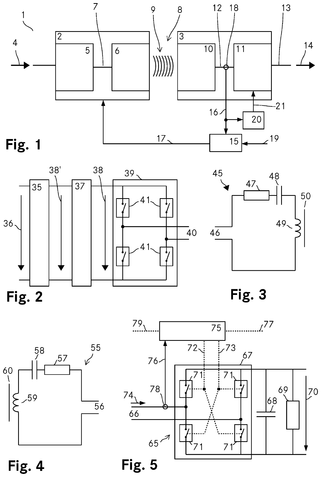
[0119]FIG. 1 shows a schematic representation of a wireless power transfer arrangement 1 according to the invention. The wireless power transfer arrangement 1 includes a primary side 2, a secondary side 3 and a power transfer controller 15. The primary side 2 includes an input stage 5 for converting an input power 4 into an AC primary output power 7 which is fed to a primary resonator 6. The primary resonator 6 induces a magnetic field 9 to wirelessly transmit power across an airgap 8. The secondary side 3 includes a secondary resonator 10 which picks up the magnetic field 9 and converts the power received through the magnetic field 9 into an AC secondary output 12. An output stage 11 AC receives the AC secondary output 12 of the secondary resonator 10 and converts the AC secondary output 12 to a DC secondary output 13 which is then provided at an output of the wireless power transfer arrangement 1 as an output power 14.

[0120]The controller 15 controls the power transfer from the pr...


PUM

PropertyMeasurementUnit
currentaaaaaaaaaa
currentaaaaaaaaaa
drain-source voltageaaaaaaaaaa

Abstract

In a wireless power transfer arrangement (1) power is wirelessly transferred from a primary side (2) to a secondary side (3) across an airgap (8) by means of a primary resonator (6) that generates a magnetic field (9) and a secondary resonator (10) that receives the power by picking up the magnetic field (9). The secondary side (3) includes an output stage (11) that receives the AC power provided by the secondary resonator (10) and generates a DC output (13) to be provided to a load. A current sensing arrangement (18) senses the AC current flowing from the secondary resonator (10) to the output stage (11) and provides a current sense signal (16) to a power transfer controller (15) that controls the power transfer of the wireless power transfer arrangement (1) based on the current sense signal (16). And the current sense signal (16) is provided to a switching controller (20) that controls the switching of a synchronous rectifier of the output stage (11) that converts the AC power (12) provided by the secondary resonator (10) to the DC output (13).

Description

TECHNICAL FIELD[0001]The invention relates to a wireless power transfer arrangement for a wireless power transfer from a primary side across an airgap to a secondary side by inductive coupling, wherein the primary side includes a power input for receiving an input power, an input stage for converting the input power to a primary AC power and a primary resonator for receiving the primary AC power and inducing a magnetic field, the secondary side includes a secondary resonator for converting the power received through the magnetic field to a secondary AC power and an output stage for converting the secondary AC power to a DC output power, the output stage includes a controllable rectifier for converting the secondary AC power to the DC output power, the wireless power transfer arrangement includes a current sensing arrangement adapted to produce a current sense signal, a power transfer controller adapted to control the wireless power transfer based on the current sense signal and a co...

Claims


Application Information

Patent Timeline
Patent Type & Authority Patents(United States)
IPC IPC(8): H02J50/12H02J50/80B60L53/12H01F27/28H01F38/14H02J7/02H02M3/335
CPCH02J50/12B60L53/12H01F27/28H01F38/14H02J7/02H02J50/80H02M3/33592H02J50/70H02M7/219H02M1/126H02M1/0009H02M7/2195Y02T10/70Y02T10/7072Y02T90/14
Inventor RICHTER, ULRICH
Owner DELTA ELECTRONICS (THAILAND) PUBLIC CO LTD
Features
  • R&D
  • Intellectual Property
  • Life Sciences
  • Materials
  • Tech Scout
  • Unparalleled Data Quality
  • Higher Quality Content
  • 60% Fewer Hallucinations
Learn More