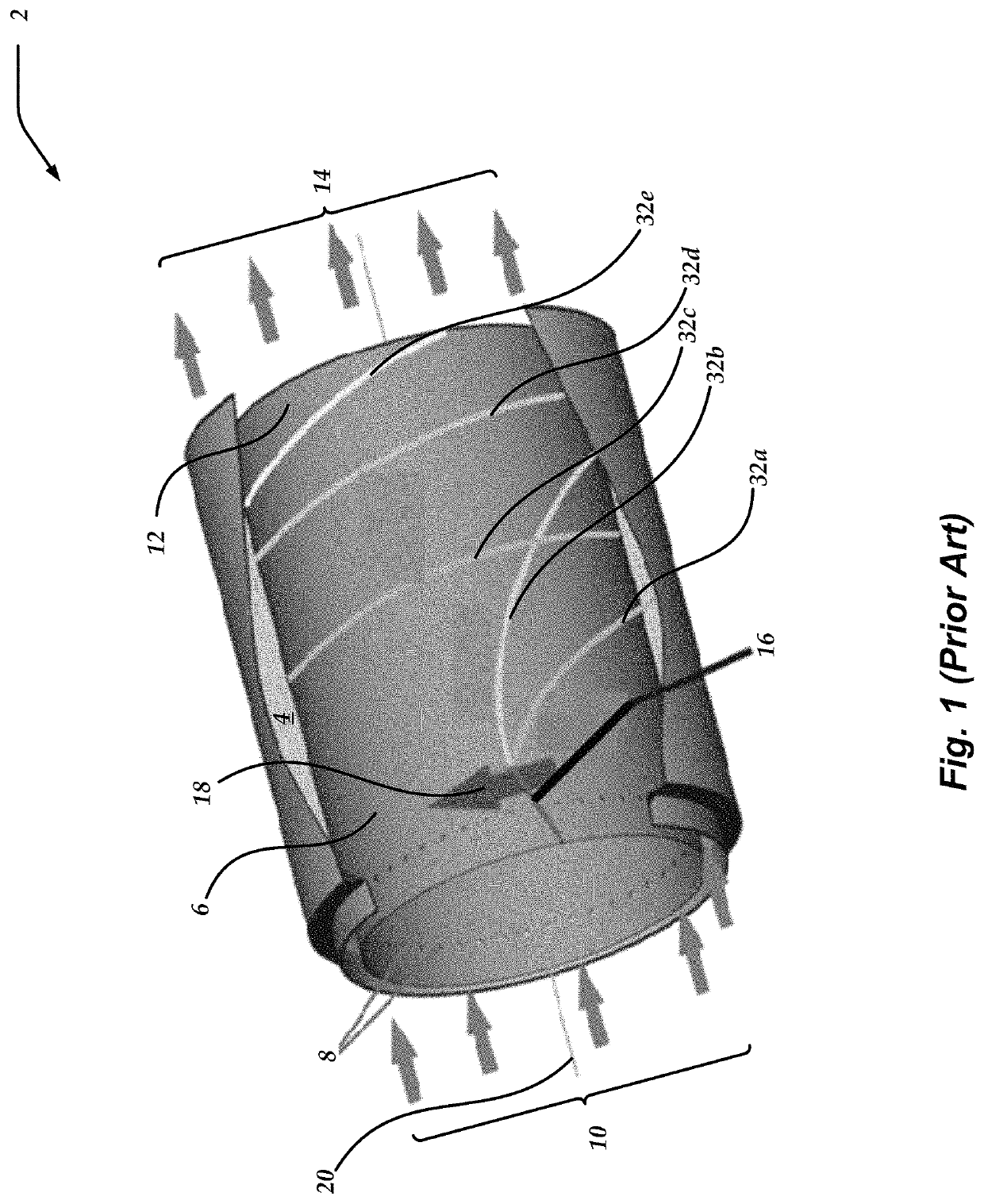
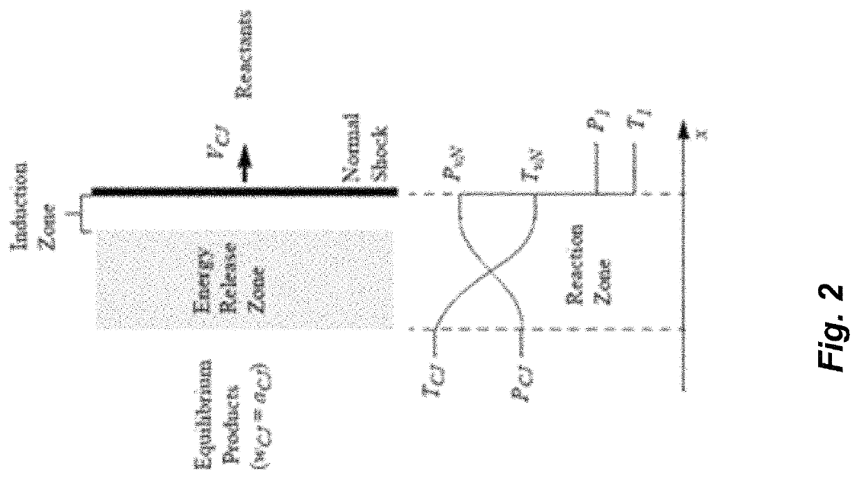
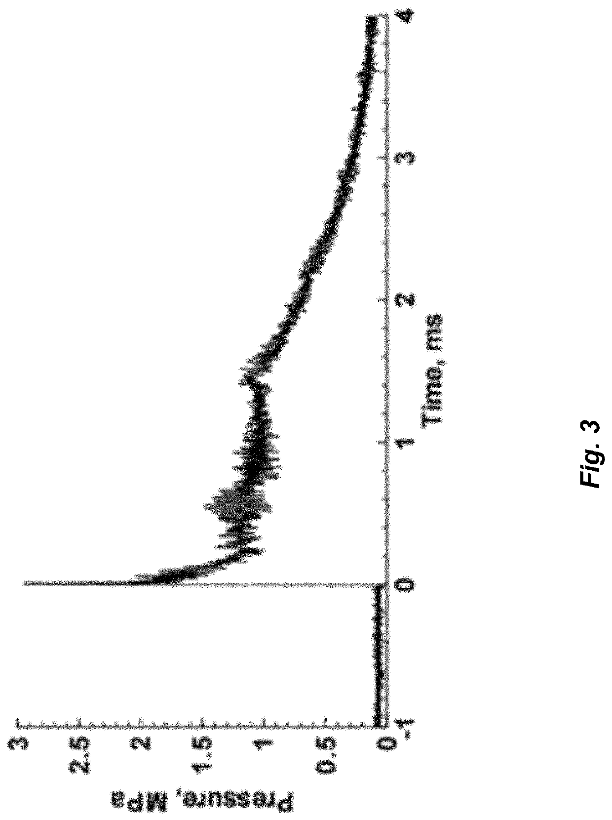
Without the flow replenishing the supply (and subsequently the necessary mixture) of unburned reactants prior to arrival of the next detonation wave, rotating detonation would be expected to cease due to the lack of supply of sufficiently mixed uncombusted reactants.
Standard liquid
rocket engines (“LREs”) are often subject to acoustic upsets such as “buzzing” or “popping”, which can cause the engines to extinguish or, in the worst case, to catastrophically destruct.
Moreover, high-speed video over these ranges reveals extremely fast adjustments in wave number.
Despite these advantages of continuous detonation engines, however, incomplete mixing of separately injected fuel and oxidizer prior to arrival of a detonation wave can result in incomplete detonation.
Such incomplete detonation can result in subsequent parasitic
deflagration of the un-combusted reactants.
Monopropellants have been used in conventional
rocket engines, but the way conventional
rocket engines utilize monopropellants is not transferable to continuous detonation engines because conventional monopropellant rocket engines that utilize monopropellants (e.g., hydrazine or
hydroxylamine nitrates (“HAN”)) operate much differently than continuous detonation engines.
Accordingly, the typical catalyst-based approach to utilizing monopropellants in conventional rocket engines is not applicable to continuous detonation engines.
Conventional wisdom is that conventional monopropellants (e.g., hydrazine, HAN, AF-M315E, LMP-103S) are very difficult or close to impossible to detonate in the vapor or gaseous phase and therefore cannot be used in continuous detonation engines.
In contrast, newer, more unstable monopropellants or pre-mixed bipropellants (e.g.,
nitrous oxide / fuel blends) are highly detonable in either phase.
The conventional wisdom is that such highly detonable fuels are too dangerous for use with continuous detonation engines.
Such barriers or arrestors, however, would be expected to fail at flashback prevention in a continuous detonation engine because such barriers or arrestors are designed to prevent
backward propagation of flames or of only a
combustion wave that occurs at only the time of initial ignition.
Accordingly, prior
flame barriers or flashback arrestors would be expected to fail at preventing flashback in a continuous detonation engine because the rapid, repeated encounters with the detonation
waves would preclude the conventional
flame barriers or flashback arrestors from sufficiently cooling to absorb the
thermal energy of the next encountered
combustion wave, eventually leading to the upstream
propellant being thermally energized to its combustion temperature.
Moreover, the inventors of prior
flame barriers or prior flashback arrestors failed to appropriately consider shock
waves in detonation
waves because the reemergence of detonation waves after
quenching combustion had not yet been discovered (see, for example, paragraphs 0047 and 0052 of U.S. Pre-Grant Publication No. 2011 / 0146231 issued to Mungas et al., which teach
quenching a detonation wave by resisting a flame front with a porous media element that absorbs
thermal energy at rates higher than the rate at which a detonation wave releases
thermal energy).
Such experiments evaluate passage of combustion waves but ignore whether a
shock wave passed through the barrier because a
shock wave traveling through fluid (in the experiment, fluid
propellant in the detonated line on the downstream side of the barrier,
ambient air in the barrier, and
ambient air the environment upstream of the barrier) generally fails to carry enough energy to cause a subsequently encountered
solid to combust (in the experiment, the combustible
solid on the upstream side of the barrier), unless the
shock wave is exceptionally strong.
Such experiments would therefore fail to detect whether a shock wave passed through the barrier such that a detonation wave could reestablish in gaseous or liquid monopropellant on the upstream side of the barrier.
Accordingly, barriers or arrestors that prevent
backward propagation of flames or combustion are insufficient to reliably prevent flashback from detonation waves if such barriers or arrestors permit passage of a shock wave.
In conventional rocket engines the only detonation wave occurs upon ignition or shutdown, so the likelihood of flashback occurring is relatively low for an arrestor that only modestly impedes shock waves.
Accordingly, given both the conventional knowledge and the disclosure in U.S.
patent application Ser. No. 17 / 343,679, it would be expected that conventional flame barriers or flame arrestors are unacceptable for safe use of detonable monopropellants such as the newer monopropellants discussed above in continuous detonation engines because of the frequent encounters with detonation waves, thereby driving up the likelihood that flashback occurs.
Conventional monopropellant rocket engines, however, have numerous drawbacks.
For example, the catalyst draws significant power for the heaters and is a major life-
limiting factor on monopropellant thrusters.
Monopropellant catalysts are also expensive and are mechanically and thermally fragile.
Further, catalyst
bed heaters required to heat the catalyst
bed to a temperature adequate to support
catalytic decomposition of the monopropellant are expensive and represent a failure mode that reduces the reliability of monopropellant thrusters.
To increase reliability, monopropellant thrusters often have redundant pairs of catalyst
bed heaters, further increasing the cost and complexity of such thrusters.
The time required to preheat catalyst beds for monopropellant thrusters is another drawback because it typically takes minutes to hours to accomplish, thereby precluding instantaneous availability of the thrusters.


