
High pressure pump for vehicle

a high-pressure pump and vehicle technology, applied in the direction of machines/engines, fuel injection apparatus, feed systems, etc., can solve the problems of reducing discharge efficiency, pistons may become stuck to one side of the cylinder, and fuel leakage, so as to reduce the amount of fuel leaking, reduce operation loss, and operate more stably

Active Publication Date: 2022-11-15
HYUNDAI KEFICO CORP
View PDF5 Cites 0 Cited by
  • Summary
  • Abstract
  • Description
  • Claims
  • Application Information

AI Technical Summary

Benefits of technology

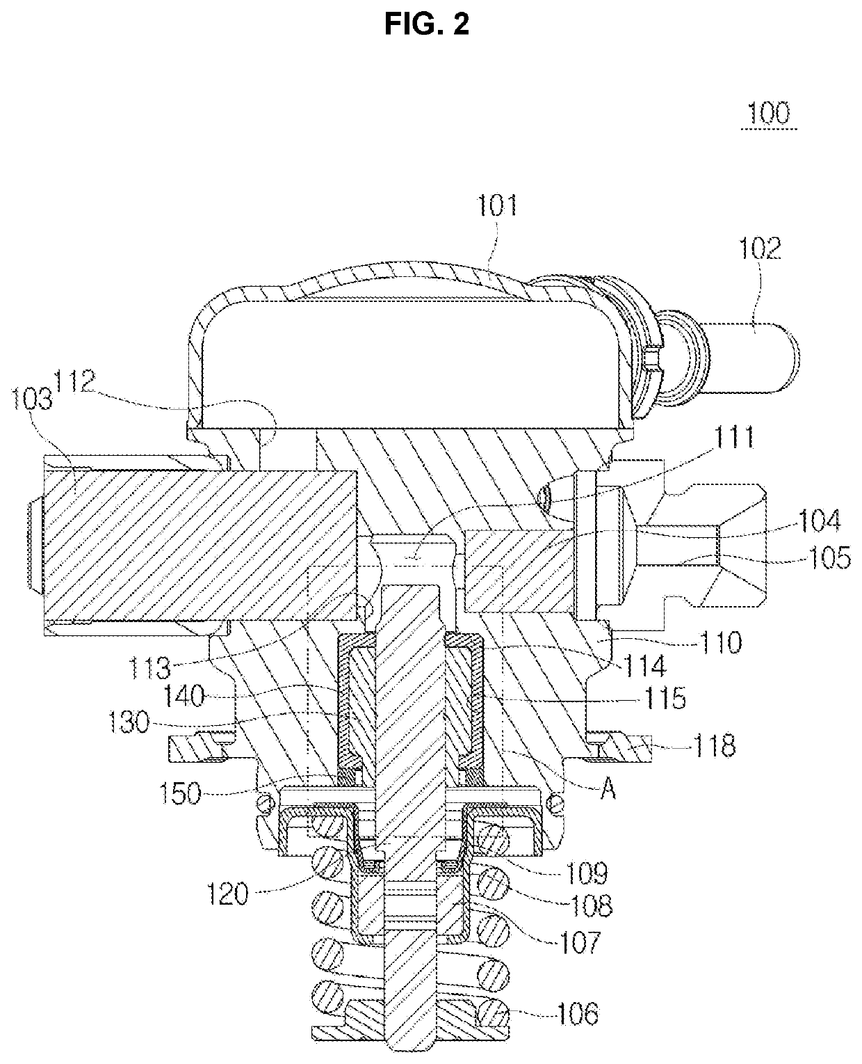
[0016]The present disclosure provides a high pressure pump configured to reduce an amount of fuel leaking through a gap between a piston and a cylinder and prevent the piston from sticking to one side of the cylinder even when a lateral force is generated during an up / down operation of the piston.
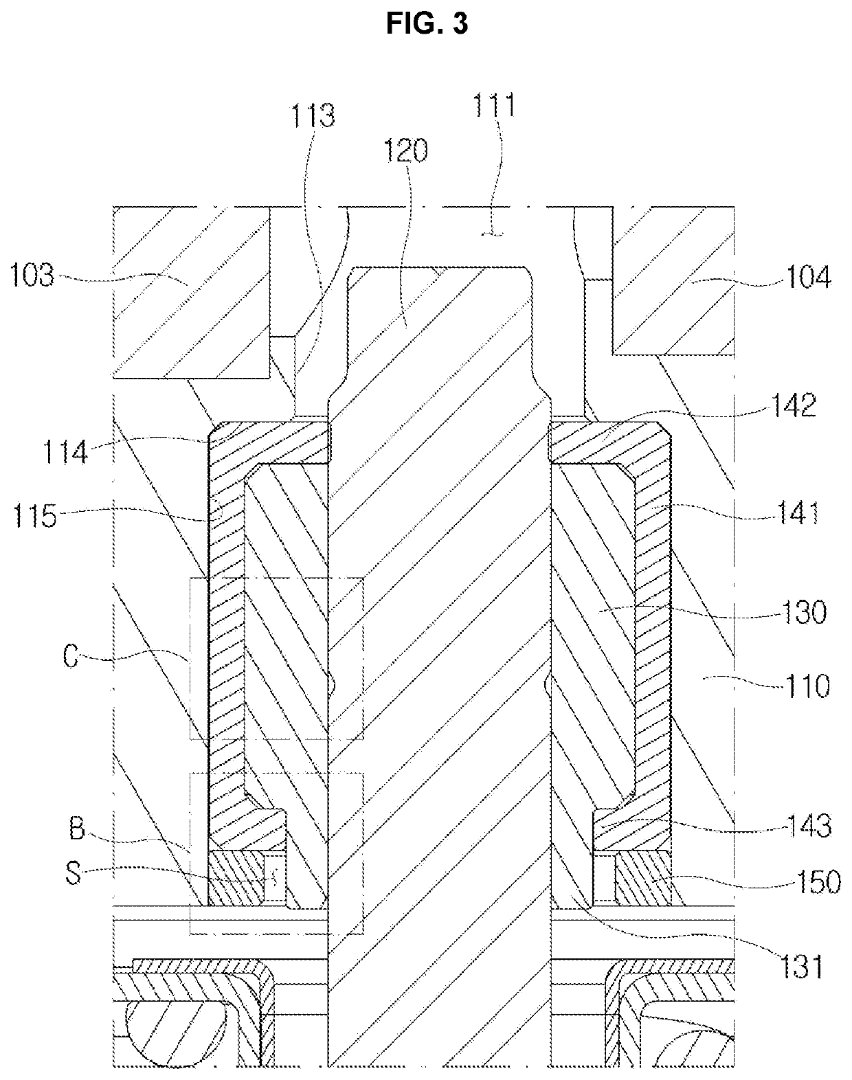
[0027]According to the present disclosure, there is an effect of reducing the fuel amount leaking through a gap between a piston and a cylinder, preventing the piston from sticking to one side of the cylinder even when a lateral force is generated during an up / down operation of the piston, and reducing operation loss caused by friction between the piston and the cylinder.
[0028]In addition, the up / down operation of the piston is guided through the support member and the cylinder so that the piston operates more stably, and there is an effect of enhancing the discharge efficiency of the high pressure pump.

Problems solved by technology

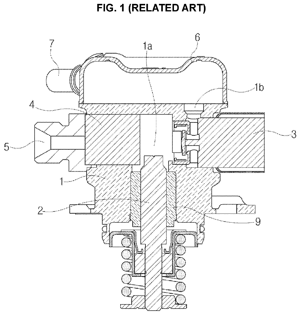
However, when the pressure of the high pressure pump rises, there may be an increase in an amount of fuel leakage through a gap between the piston and the cylinder, thereby reducing discharge efficiency.
In addition, generation of a lateral force during the up / down operation of the piston causes another problem in that the piston may become stuck to one side of the cylinder in the direction of the lateral force generation.
In particular, there may be a problem in that a risk of sticking increased as the pressure of the high pressure pump rises.
In addition, there may be a further problem in that the risk of sticking between the piston and the cylinder increases when the gap between the piston and the cylinder is reduced to prevent lowering of the discharge efficiency caused by the leakage.
In addition, securing the gap between the piston and the cylinder to prevent sticking may increase the leakage amount, thereby reducing the discharge efficiency.

Method used


Image

  • High pressure pump for vehicle
  • High pressure pump for vehicle
  • High pressure pump for vehicle

Examples


Embodiment Construction

[0035]It is understood that the term “vehicle” or “vehicular” or other similar term as used herein is inclusive of motor vehicles in general such as passenger automobiles including sports utility vehicles (SUV), buses, trucks, various commercial vehicles, watercraft including a variety of boats and ships, aircraft, and the like, and includes hybrid vehicles, electric vehicles, plug-in hybrid electric vehicles, hydrogen-powered vehicles and other alternative fuel vehicles (e.g. fuels derived from resources other than petroleum). As referred to herein, a hybrid vehicle is a vehicle that has two or more sources of power, for example both gasoline-powered and electric-powered vehicles.

[0036]The terminology used herein is for the purpose of describing particular embodiments only and is not intended to be limiting of the disclosure. As used herein, the singular forms “a,”“an” and “the” are intended to include the plural forms as well, unless the context clearly indicates otherwise. It wil...


PUM


Abstract

A high pressure pump includes a housing with a chamber formed inside and a flow control valve and a discharge check valve installed in the chamber; a piston installed to operate up and down in an assembly hall formed in the housing to compress fuel in the chamber to a high pressure; a cylinder forming a gap between an inner circumferential surface and the piston and guiding reciprocation of the piston; and a support member seated on a stepped surface of the housing to surround an outside of the cylinder and configured to elastically support the housing and the cylinder, thereby reducing friction while preventing fuel leakage between the piston and the cylinder.

Description

CROSS-REFERENCE TO RELATED APPLICATION(S)[0001]This application claims under 35 U.S.C. § 119 the benefit of Korean Patent Application No. 10-2020-0112137 filed on Sep. 3, 2020, the entire contents of which are incorporated herein by reference.BACKGROUND(a) Technical Field[0002]The present disclosure relates to a high pressure pump, more particularly, to the high pressure pump provided with a support member between a housing and a cylinder to prevent fuel leakage between a piston and the cylinder and prevent the piston from sticking to the cylinder.(b) Description of the Related Art[0003]A high pressure pump is connected to a fuel rail, and a low pressure pump is installed inside a fuel tank.[0004]Fuel is first compressed by the low pressure pump to be pumped to the high pressure pump through a fuel hose, is compressed again at a high pressure in the high pressure pump to be supplied to the fuel rail and is injected from the fuel rail to a combustion chamber through each injector.[00...

Claims


Application Information

Patent Timeline
Patent Type & Authority Patents(United States)
IPC IPC(8): F02M59/44F02M63/00F02M55/02F02M59/10
CPCF02M59/442F02M59/10F02M63/0054F02M55/025F02M59/445F02M2200/16
Inventor HAN, KYUNG CHULPARK, HYEONG KYUNKIM, JIN SUNG
Owner HYUNDAI KEFICO CORP
Learn More