
Laminated film roll and method of producing the same

a technology of laminated film and rolling pin, which is applied in the field of laminated film rolls, can solve the problems of time and trouble in production, the layer cannot be formed on a soft resin film, and the inability to produce continuous rolls in the shape of rolls, etc., and achieves the effect of low cost and ultra-low refractive index

Active Publication Date: 2022-11-22
NITTO DENKO CORP
View PDF160 Cites 0 Cited by
  • Summary
  • Abstract
  • Description
  • Claims
  • Application Information

AI Technical Summary

Benefits of technology

The present invention provides a laminated film roll with an ultra-low refractive index layer that can substitute for air layers and allow for continuous production. This results in a cost-effective, ultra-low refractive index solution useful for optical elements that require this property.

Problems solved by technology

Forming air layers in such a manner, however, requires to dispose the components at regular spacings, which prevents the components from being stacked sequentially and causes time and trouble in production.
These methods, however, have the following problem.
Since the thus obtained void-provided layer is inferior in flexibility, the layer cannot be formed on a soft resin film, which does not allow continuous production in the shape of a roll.
This method, however, has the following problem.
Since the thus obtained void-provided layer is inferior in film strength, an impact resistance cannot be imparted, which does not allow continuous production in the shape of a roll.
These methods, however, have the following problem.

Method used


Image

  • Laminated film roll and method of producing the same
  • Laminated film roll and method of producing the same
  • Laminated film roll and method of producing the same

Examples


example 1

[0178]In the present example, an ultra-low refractive index layer of the present invention was produced as described below.

[0179](1) Gelation of Silicon Compound

[0180]0.95 g of MTMS which is the precursor of a silicon compound was dissolved in 2.2 g of DMSO. 0.5 g of 0.01 mol / L oxalic acid aqueous solution was added to the mixture, and the resultant was stirred at room temperature for 30 minutes to hydrolyze MTMS, thereby preparing tris(hydroxy)methylsilane.

[0181]0.38 g of ammonia water having a concentration of 28% and 0.2 g of pure water were added to 5.5 g of DMSO, then the aforementioned mixture that had been subjected to the hydrolysis treatment was added thereto, and the resultant was stirred at room temperature for 15 minutes to gelate tris(hydroxy)methylsilane, thereby obtaining a gelled silicon compound.

[0182](2) Aging Treatment

[0183]The aging treatment was carried out as follows. The mixture that had been subjected to the gelation treatment was incubated at 40° C. for 20 h...

example 2

[0191]A silicone porous body was formed in the same manner as in Example 1 except that the amount of ammonia water, which is a catalyst, was reduced to 0.09 g in gelation of silicon compound precursor MTMS, which is a raw material and the conditions for the incubation in the aging step were changed from at 40° C. for 20 hours to at room temperature for 2 hours. Then, the properties of the silicone porous body were measured.

example 3

[0196]In the present example, an ultra-low refractive index layer of the present invention was produced as described below.

[0197]The “(1) gelation of silicon compound” and the “(2) aging treatment” were carried out in the same manner as in Example 1. Subsequently, the “(3) pulverizing treatment” was carried out in the same manner as in Example 1 except that an isopropyl alcohol (IPA) solution containing 1.5 wt % photobase generation catalyst (product of Wako Pure Chemical Industries, Ltd., product name: WPBG 266) instead of 0.3 wt % KOH aqueous solution was added to the sol particle liquid, thereby preparing a coating liquid. The amount of the IPA solution containing the photobase generation catalyst to be added relative to 0.75 g of the sol particle liquid was 0.031 g. Then, the “(4) formation of coating film and formation of silicone porous body roll” were carried out in the same manner as in Example 1. The porous body obtained in this manner after drying was irradiated with UV. T...


PUM

PropertyMeasurementUnit
volume average particle sizeaaaaaaaaaa
refractive indexaaaaaaaaaa
pore sizeaaaaaaaaaa

Abstract

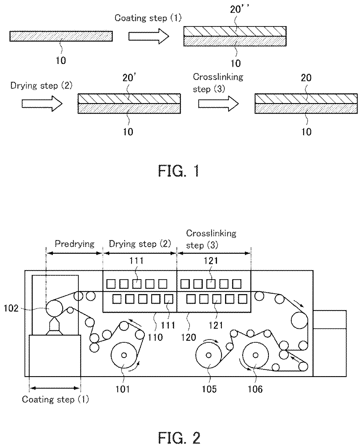
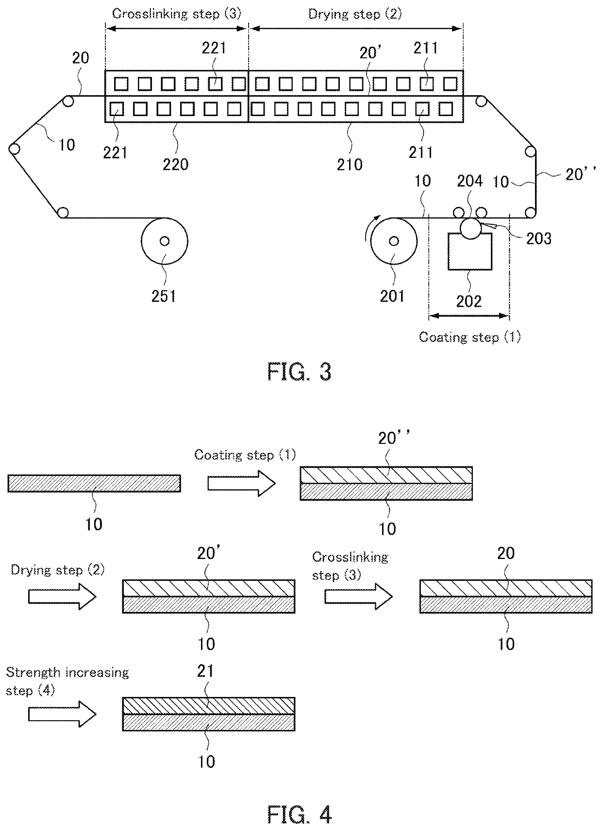
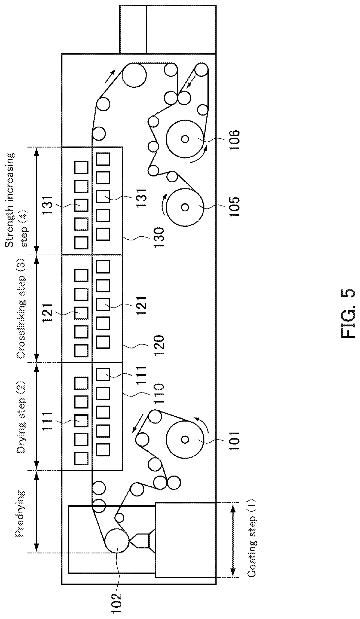
The present invention provides a new member having a low refractive index as a substitute for an air layer, for example. The laminated film roll of the present invention includes a long laminated film roll including: an ultra-low refractive index layer having a refractive index of 1.20 or less; and a resin film, wherein the ultra-low refractive index layer is stacked on the resin film. The method of forming the long laminated film roll of the present invention includes steps of: preparing a liquid containing microporous particles; coating a resin film with the liquid; and drying the liquid applied on the resin film, for example.

Description

TECHNICAL FIELD[0001]The present invention relates to a laminated film roll and a method of producing the same.BACKGROUND ART[0002]Disposing two substrates at a regular spacing forms an air layer which is a void space between the substrates. The air layer formed between the substrates serves as a low refractive layer that reflects light entirely, for example. Thus, for example, in the case of an optical film, components such as a prism, a polarizing film, and a polarizing plate are disposed at regular spacings to provide air layers each of which serves as a low refractive index layer between the components. Forming air layers in such a manner, however, requires to dispose the components at regular spacings, which prevents the components from being stacked sequentially and causes time and trouble in production.[0003]For solving such problems, there are attempts to develop a member such as a film having a low refractive index as a substitute for an air layer which is a void space betw...

Claims


Application Information

Patent Timeline
Patent Type & Authority Patents(United States)
IPC IPC(8): C08J7/043B32B27/06C08J7/04C08J7/046B32B5/18B32B37/14G02B1/10
CPCC08J7/043B32B5/18B32B27/06B32B37/14C08J7/046C08J7/0427G02B1/10B32B2551/00C08J2483/04B05D7/24B32B7/023G02B1/11
Inventor HARUTA, HIROMOTOTAKEMOTO, HIROYUKIHATTORI, DAISUKENAKAMURA, KOZO
Owner NITTO DENKO CORP
Learn More