Photocathode

a photocathode and cathode technology, applied in the field of photocathodes, can solve the problems that the characteristics of the group iii-v nitride semiconductor layer cannot be improved by rapid heat treatment, and the substrate of apphire substrate is difficult to be heated at a high speed in the manufacture of photocathodes

Inactive Publication Date: 2001-05-17
HAMAMATSU PHOTONICS KK
View PDF0 Cites 16 Cited by
  • Summary
  • Abstract
  • Description
  • Claims
  • Application Information

AI Technical Summary

Problems solved by technology

However, for not having a high absorbance for infrared rays, a sapphire substrate is difficult to be heated at a high speed in manufacturing t...

Method used


Image

  • Photocathode
  • Photocathode
  • Photocathode

Examples


Embodiment Construction

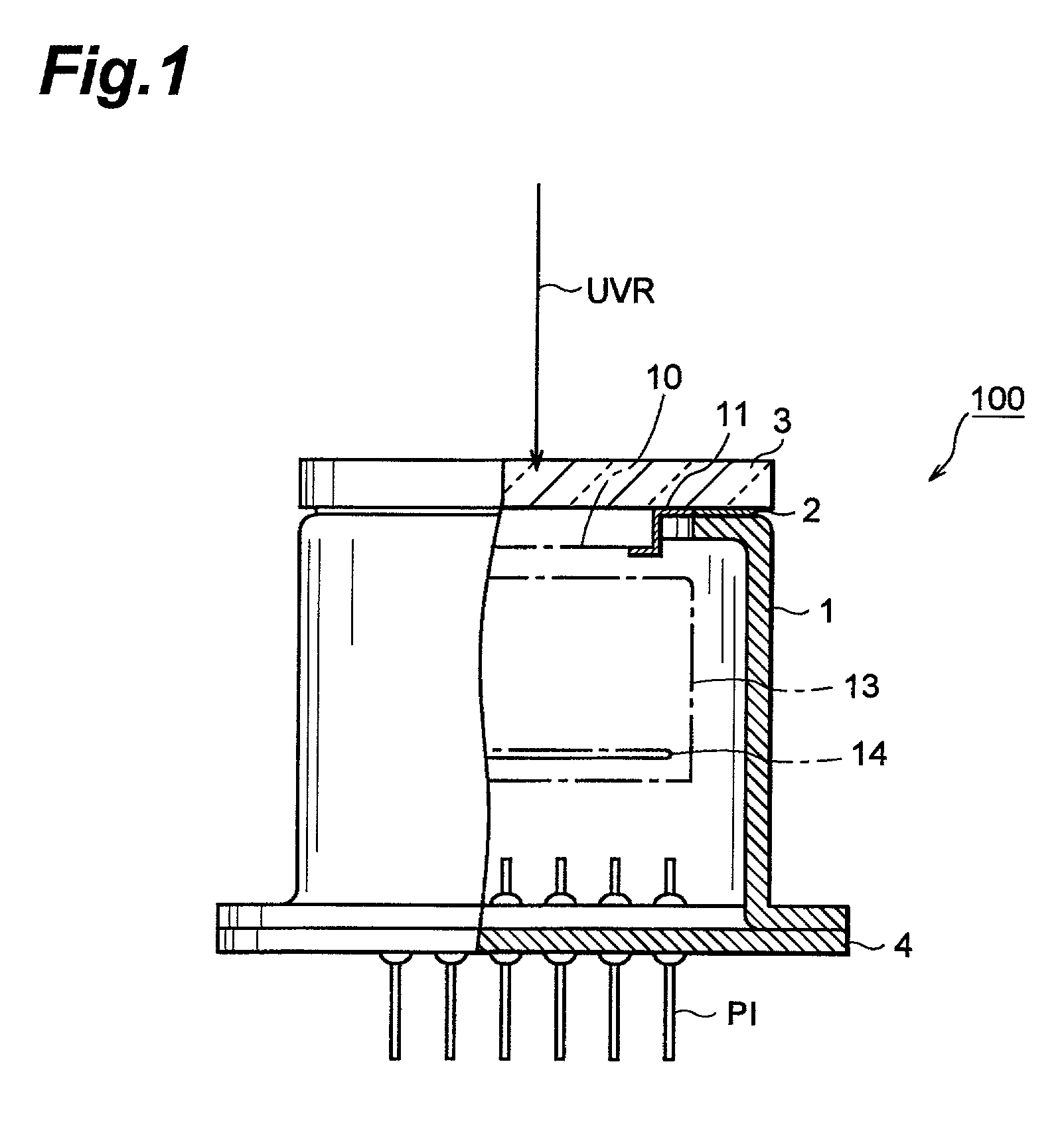
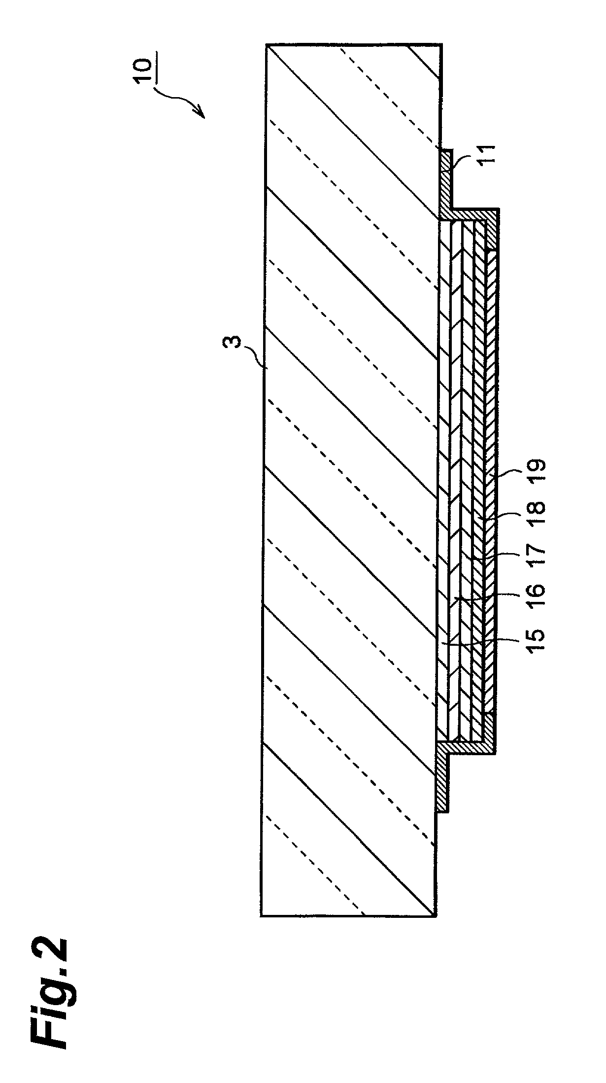
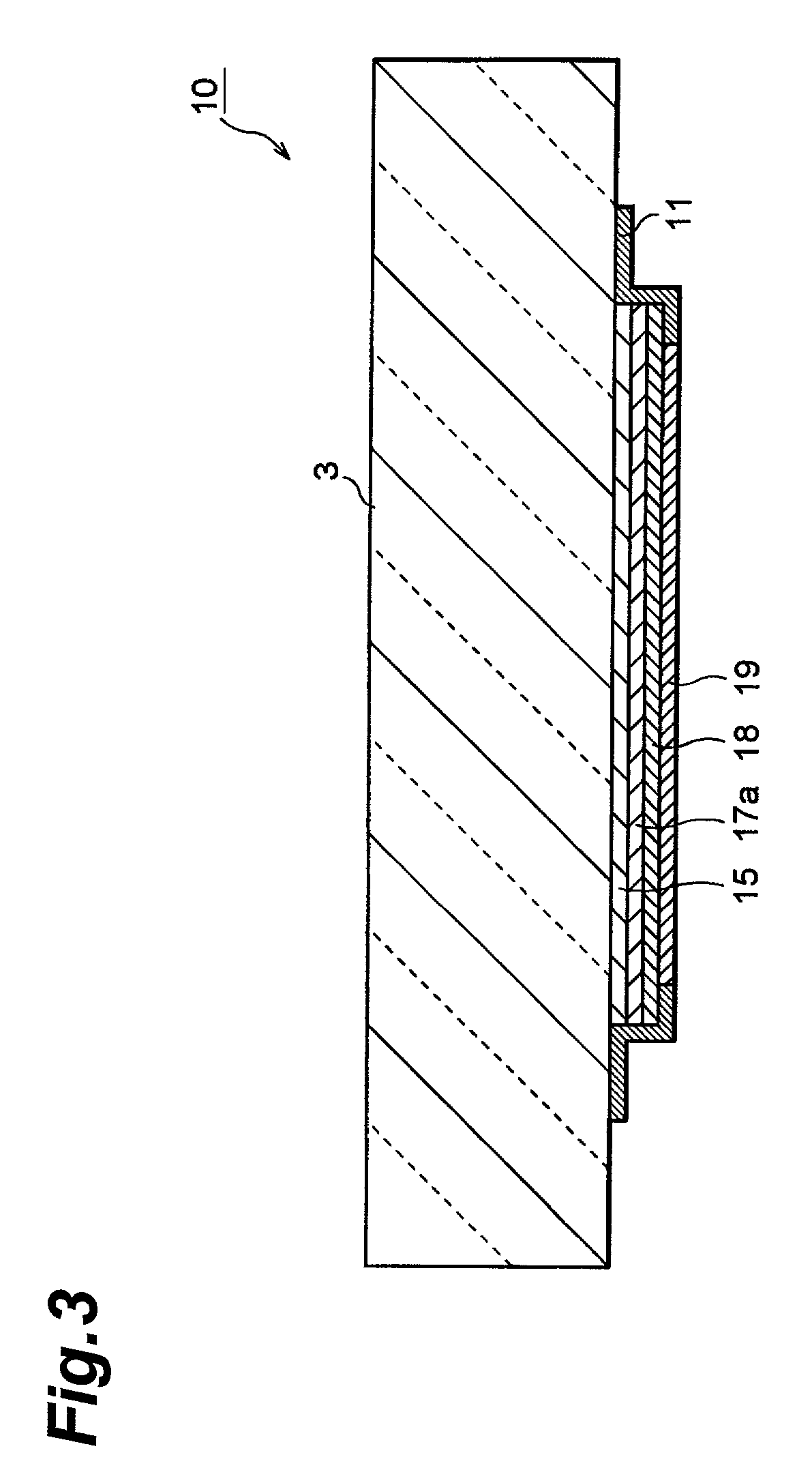
17. A photocathode according to an embodiment of the present invention will be described hereinbelow. Like reference numerals will refer to like parts or the parts having like functions and overlapping explanations will be omitted. FIG. 1 is an elevational view, partly in cross-section, illustrating a photomultiplier tube 100 employing a photocathode of the present invention. The photomultiplier tube 100 includes a side tube 1 made of a metal, a UV glass substrate 3 sealing one opening of the side tube 1 with an In sealing material 2 interposed therebetween, and a bottom plate 4 sealing the other opening of the side tube 1 and provides a vacuum environment (a reduced pressure environment of 100 Torr (13332.24 Pa) or less) therewithin. A laminate 10 composed of a plurality of layers is provided on the surface of the UV glass substrate 3 inside the side tube 1. The UV glass substrate 3 and the laminate 10 constitute the photocathode.

18. The laminate 10 is electrically connected to the...


PUM


Abstract

A photocathode having a UV glass substrate and a laminate composed of a SiO2 layer, a GaAlN layer, a Group III-V nitride semiconductor layer and an AlN buffer layer provided on the UV glass substrate in succession. The UV glass substrate, which absorbs infrared rays, can be heat treated at a high speed by photoheating. Further, the UV glass substrate, which is transparent to ultraviolet rays, permits ultraviolet rays to be introduced into the Group III-V nitride semiconductor layer where photoelectric conversion occurs.

Description

1. This is a continuation-in-part application of application serial no. PCT / JP98 / 02837 filed on Jun. 25, 1998, now pending.2. 1. Field of the Invention3. The present invention relates to a photocathode which is applicable to an image intensifier or a photomultiplier tube.4. 2. Related Background Art5. Conventional photocathodes employing GaN are disclosed in Japanese Patent Application Laid-Open No. S61-267374 (U.S. Pat. No. 4,618,248), Japanese Patent Application Laid-Open No. H8-96705, U.S. Pat. No. 5,557,167 and U.S. Pat. No. 3,986,065. Such photocathodes have a sapphire substrate and a superlattice structure of AlGaN formed on the sapphire substrate.6. The detection sensitivity of an electron tube employing a photocathode having a Group III-V nitride semiconductor layer (semiconductor layer of a nitride containing one or more elements selected from groups III-V of the periodic table), such as a GaN semiconductor layer, formed on a sapphire substrate depends on the crystallinity ...

Claims


Application Information

Patent Timeline
IPC IPC(8): H01J1/34H01J43/08
CPCH01J1/34H01J43/08H01J2201/3423H01J2231/50021
Inventor NIHASHI, TOKUAKI
Owner HAMAMATSU PHOTONICS KK
Why Eureka
Try Eureka