Capacitive voltage divider for measuring high voltage pulses with millisecond pulse duration

a technology of capacitive voltage divider and millisecond pulse duration, which is applied in the direction of voltage divider, measurement device, instruments, etc., can solve the problems of not being suitable for measuring pulses, measuring errors that can reach 15% and even more, and may well be several percent of the measurement error occurring with temperature changes, so as to improve the accuracy of voltage measurement at the end of rectangular pulse with millisecond duration and high dielectric strength

Inactive Publication Date: 2001-06-14
KERNFORSCHUNGSZENTRUM KARLSRUHE GMBH
View PDF0 Cites 20 Cited by
  • Summary
  • Abstract
  • Description
  • Claims
  • Application Information

AI Technical Summary

Benefits of technology

0015] Preferably, the high voltage cascade is disposed in a dielectric medium at least up to the condenser with the lowest potential. With an appropriate containment, the dielectric medium of the cascade of the high voltage divider may be pressurized particularly with a compact structure, which provides for high dielectric strength.
0016] The advantage of such a voltage divider is that immediately after applying a

Problems solved by technology

The measuring error occurring with temperature changes may well be several percent.
However, it is not suitable for measuring pulses in the millisecond range

Method used


Image

  • Capacitive voltage divider for measuring high voltage pulses with millisecond pulse duration
  • Capacitive voltage divider for measuring high voltage pulses with millisecond pulse duration

Examples


Embodiment Construction

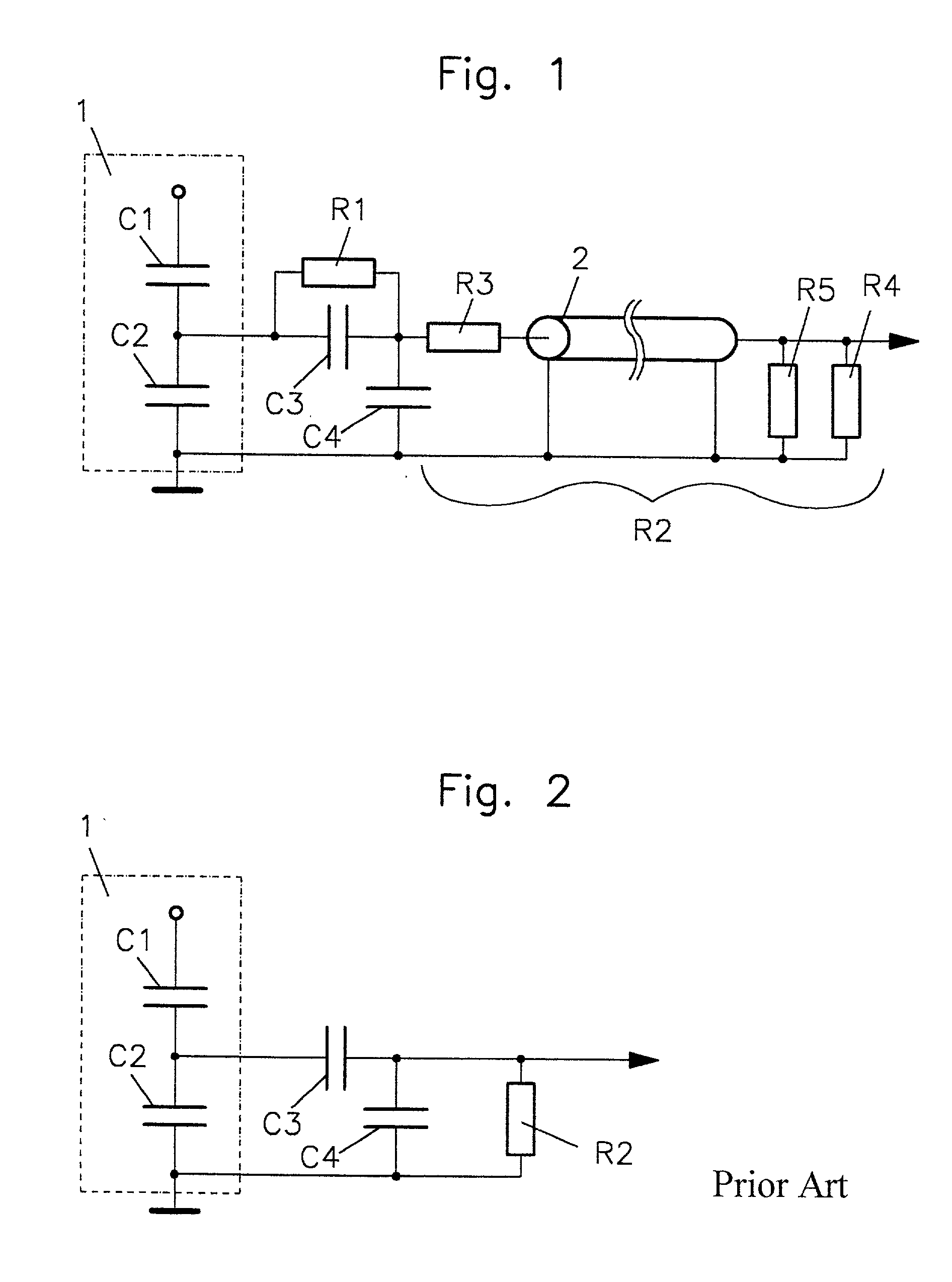
[0021] As shown in FIG. 1, the high voltage part 1 of the high voltage divider comprises one or--depending on the dielectric strength--at least two condensers C1, which are arranged in series. They are usually disposed in a pressurized insulating gas or insulating oil such as transformer oil or another suitable insulating medium. The low voltage part C2 is for example a plate condenser which is disposed in the same compartment as the high voltage part 1. In this way, the cascade C1, C2 of the high voltage divider is exposed everywhere to the same temperature such that there is no effect caused by different temperatures.

[0022] The measuring voltage divider comprises a cascade of serially arranged commercially available condensers C3 and C4 disposed in the circuit between the common potential point of the condensers C1 and C2 and the reference potential. I this case the reference potential is ground potential to which also the high voltage divider is connected.

[0023] Basically, the hi...


PUM


Abstract

In a capacitive voltage divider for measuring high voltage pulses with millisecond pulse duration comprising a high voltage divider including a first cascade of at least two serially arranged condensers of which one (C1) is disposed at the high potential end and another (C2) is disposed at the low potential end of the cascade, and a measuring voltage divider connected to the other condenser (C2) and including a second cascade of at least first and second serially arranged condensers (C3, C4) arranged, respectively, at the high and low potential ends of the second cascade with the second condenser being connected with its low voltage side to a signal supply line leading to a measuring device, and an ohmic resistor (R1) arranged in parallel with the first condenser and a resistance (R2) connected to the one and first condensers in parallel with the second condenser (C4), the ohmic resistor (R1) is so dimensioned that 1.1<C4*R2/C3*R1<1.15.

Description

[0001] This is a continuation-in-part application of international application PCT / EP99 / 04772 filed Jul. 07, 1999 and claiming the priorities of German applications 198 33 179.7 filed Jul 23, 1998 and 199 23 211.3 filed May 02, 1999.BACKGROUND OF THE INVENTION[0002] The invention resides in a capacitive voltage divider for measuring high voltage pulses with millisecond impulse duration.[0003] For measuring high voltage pulses in the nano- and microsecond range, simple capacitive voltage dividers are used. The high voltage part of such a divider consists generally of at least one cylindrical condenser, which is disposed within a pressurized insulating gas or an insulating oil. Depending on the desired divider ratio K, the low voltage part of the high voltage divider may be disposed in the same space as the high voltage part (about K<100) or it may be arranged separately therefrom (about K>100). With commercially manufactured condensers, the voltage divider is generally designed...

Claims


Application Information

Patent Timeline
IPC IPC(8): G01R15/06G01R27/26G01R29/02
CPCG01R15/06
Inventor KUPERMAN, GRIGORYJUNGST, KLAUS-PETERSALBERT, HEINRICH
Owner KERNFORSCHUNGSZENTRUM KARLSRUHE GMBH
Why Eureka
Try Eureka