Fuel injection system for internal combustion engine

a fuel injection system and internal combustion engine technology, applied in the direction of liquid fuel feeders, machines/engines, electric control, etc., can solve the problems of time lag (transport lag) until, improve productivity, and become a problem

Inactive Publication Date: 2001-09-27
HITACHI LTD +1
View PDF0 Cites 29 Cited by
  • Summary
  • Abstract
  • Description
  • Claims
  • Application Information

AI Technical Summary

Problems solved by technology

Therefore, the fuel spray shape varying means using the piezoelectric element needs to be formed in a very narrow space of a nozzle end portion of the fuel injector, which causes a problem of improving the productivity.
In addition, the problem of reliability such as change in characteristic and durability ...

Method used


Image

  • Fuel injection system for internal combustion engine
  • Fuel injection system for internal combustion engine
  • Fuel injection system for internal combustion engine

Examples


Embodiment Construction

[0024] An embodiment of a fuel injection system for an internal combustion engine in accordance with the present invention will be described below in detail, referring to the accompanied drawings.

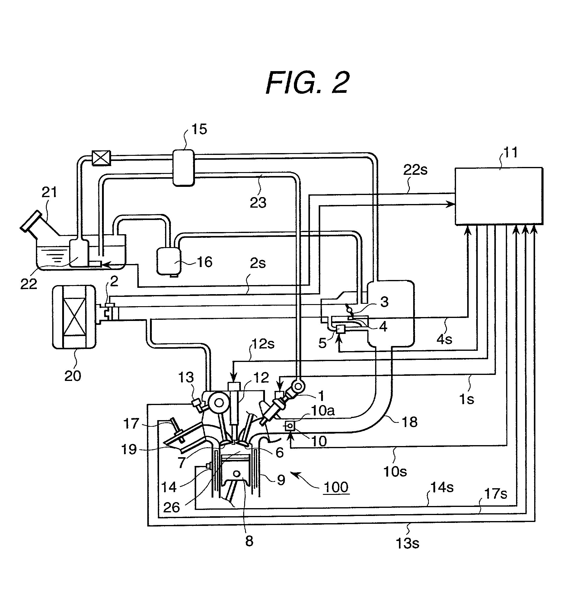
[0025] Initially, the whole construction of the engine control system comprising the embodiment of the fuel injection system (the fuel injector 1) in accordance with the present invention will be described, referring to FIG. 2.

[0026] In each of cylinders 9 of an internal combustion engine 100 composed of four cylinders (only one of the four cylinders is illustrated in the figure), a combustion chamber is formed by arranging an ignition plug 12, and an intake valve 6 and an exhaust valve 7, and a piston 8 reciprocally moving in the cylinder 9. In this embodiment, the engine is of a 4-cylinder engine, but number of the cylinders is not limited to four. In each of the cylinders 9, an intake manifold 18 and an exhaust manifold 19 opened and closed by the intake valve 6 and the exhaust valve 7 r...


PUM


Abstract

In a port fuel injection lean burn engine, attaching of fuel spray onto a wall surface, which is a problem at atomizing injected fuel, is reduced, and the quality and shaping state of the mixed gas in cylinders of the engine is improved. The engine comprises a fuel injector 1; an intake valve 6 for opening and closing an intake port; and an intake air flow control device 10. The injected fuel is shaped in a low penetration fuel spray when the engine is operated in a low load and low rotation speed, and the injected fuel is shaped in a high penetration fuel spray when the engine is operated in a high load and high rotation speed. The fuel is injected in synchronism with the intake stroke of the engine, and is transported by the air flow flowing through the intake air flow control device 10 to suppress attaching of fuel spray onto a wall surface.

Description

[0001] 1. Field of the Invention[0002] The present invention relates to a fuel injection system for an internal combustion engine, and particularly to a technology for controlling fuel to attach onto a wall surface of an intake manifold by controlling penetration of fuel spray (fuel spray travel).[0003] 2. Prior Art[0004] As a known conventional fuel injection system, a system is disclosed in Japanese Patent Application Laid-Open No.5-126012. In this publication, it is described that since rotation speed of an engine is low and closing time of the intake valve is long when the engine is operated in a low speed range such as at starting operation or at idling operation, the fuel spray from the fuel injector of electromagnetic type is preferably suspended inside the intake manifold, and the penetration force of the fuel spray is preferably weak and the fuel becomes fine liquid droplets.[0005] It is also described that on the other hand, since rotation speed of the engine is high and c...

Claims


Application Information

Patent Timeline
IPC IPC(8): F02B31/00F02B31/06F02D41/00F02D41/04F02D41/20F02M51/08F02M61/12F02M69/00
CPCF02B31/06F02D41/20F02D2041/2034F02D2041/2051Y02T10/146Y02T10/12F02M61/12
Inventor OKAMOTO, YOSHIOKADOMUKAI, YUZOMIYAJIMA, AYUMUNAGANO, MASAMISOMENO, TADASHI
Owner HITACHI LTD
Why Eureka
Try Eureka