
Tissue press and system

a tissue press and tissue technology, applied in the field of tissue press and system, can solve the problems of reducing the holding power of the graft and the ingrowth ability of the gra

Inactive Publication Date: 2001-10-04
BONUTTI SKELETAL INNOVATIONS +1
View PDF0 Cites 28 Cited by
  • Summary
  • Abstract
  • Description
  • Claims
  • Application Information

AI Technical Summary

Benefits of technology

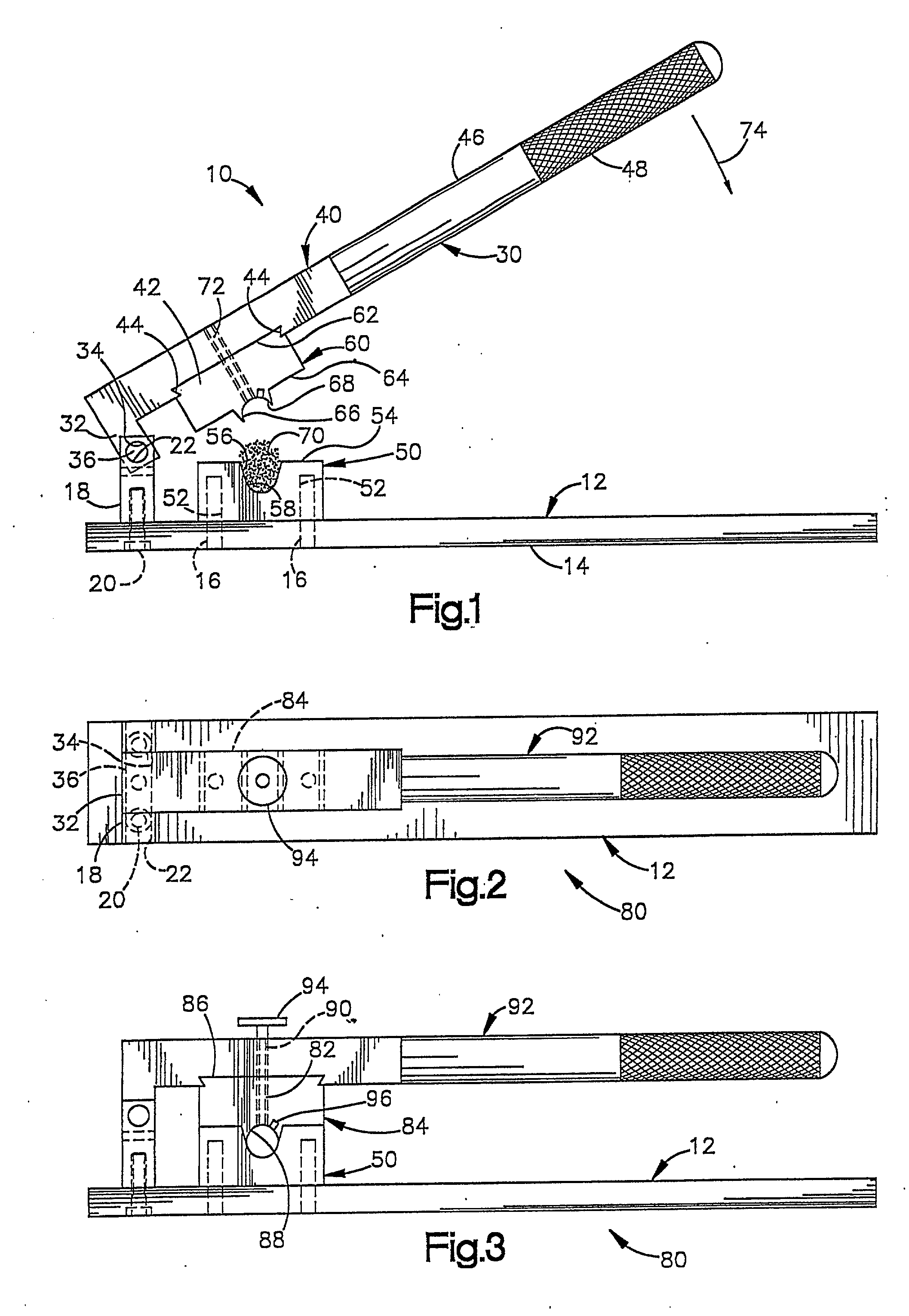
[0010] Often, reshaping of graft tissue is necessary to obtain the best possible graft. For example, in an anterior cruciate ligament reconstruction, the graft material which is removed usually has a triangular cross-sectional configuration. This graft material is placed in an opening in bone formed by drilling with a round drill. When the triangular graft material is placed in the round opening, there is minimal physical contact between the graft material and the surrounding bone. This reduces the holding power of the graft and also reduces the ingrowth ability of the graft.
[0027] A separate device or structure can be used to maintain graft tissue in the compressed state prior to and during implantation. This separate device or structure can be a mesh sack, a ring around a cylindrically shaped graft material, etc. This additional retainer structure can assist the surgeon in introducing the graft tissue into the body in the compacted condition, to provide a denser stronger graft and to allow imbibition for creating a mechanical interlock. The retainer can be made of a material which expands when placed in the body, to provide a mechanical interlock for the graft tissue.

Problems solved by technology

This reduces the holding power of the graft and also reduces the ingrowth ability of the graft.

Method used


Image

  • Tissue press and system
  • Tissue press and system
  • Tissue press and system

Examples


second embodiment

[0059] In the invention, illustrated in FIG. 5, a tissue press 150 is fluid operated (pneumatic or hydraulic) rather than manually operated. The press 150 includes a base 152 having a support surface 154 for supporting the base 152 and thus the press 150 on a table or other support (not shown). A first forming element 156 is attached to the base 152. The first forming element 156 may be slidably or otherwise attached to the base 152 in any suitable manner which blocks movement of the forming element 156 relative to the base 152 during operation of the press 150 and which allows for easy interchange of forming elements 156. The first forming element 156 has an upwardly facing forming surface 158. A fluid drain opening 160 is in fluid communication with the forming surface 158 of the first forming element 156.

[0060] An air or hydraulic cylinder 170 is fixed to the base 152 above the first forming element 156. The cylinder 170 has a port 172 for the introduction of air or other fluid u...

third embodiment

[0066] In the invention, illustrated in FIG. 6, a tissue press 200 includes a base 202 having a support surface 204 for supporting the base 202 and thus the press 200 on a table or other support (not shown). A first forming element 206 is attached to the base 202. The first forming element 206 may be slidably or otherwise attached to the base 202 in any suitable manner. The first forming element 206 includes a plurality of first fingers 208 which together have a forming surface 210 to progressively compress bone or other tissue into a predetermined shape.

[0067] An upper arm 220 is pivotally mounted to the base 202 by a pivot pin 222. A second forming element 224 is connected to the upper arm 220 in a suitable manner. The second forming element 224 includes a plurality of second fingers 226 which together have a forming surface 228 facing the forming surface 210 on the first forming element 206. The second fingers 226 are interdigitable with the first fingers 208.

[0068] In operation ...

fourth embodiment

[0079] In the invention, illustrated in FIG. 8, a tissue press 250 is operated to extrude rather than press material. The press 250 includes a base 252 having a support surface 254 for supporting the base 252 and thus the press 250 on a table or other support (not shown). A die 256 is attached to the base 252. The die 256 may be slidably or otherwise attached to the base 252 in any suitable manner which blocks movement of the die 256 relative to the base 252 during operation of the press 250 and which allows for easy interchange of forming elements 256. The die 256 has an upwardly facing opening 258. An extrusion opening 260 is in fluid communication with the opening 258 of the die 256.

[0080] An air or hydraulic cylinder 270 is fixed to the base 252 above the die 156. The cylinder 270 has a port 272 for the introduction of air or other fluid under pressure to operate a piston 274 in a known manner. A ram 280 is connected to the piston 274. The ram 280 has a surface 282 facing the op...


PUM

PropertyMeasurementUnit
shapeaaaaaaaaaa
pressureaaaaaaaaaa
compressaaaaaaaaaa

Abstract

A tissue press for shaping or compressing a piece of tissue comprises first and second members movable relative to each other. A first forming element of a predetermined shape is selectively engageable on the first member. A second forming element of predetermined shape is selectively engageable on the second member. The first and second forming elements are positionable on opposite sides of the piece of tissue. The first and second members are relatively movable between a first spaced apart condition and a second condition in which the piece of tissue is held between the first and second forming elements. Means are preferably provided for monitoring and controlling the amount of pressure applied to the piece of tissue, in order to maintain the tissue in a viable living condition. Means may also be provided for draining off fluid from compressed tissue, so that the tissue can be implanted in a compressed state and imbibe fluid from the host site. A retainer, which may be expandable, can be used to maintain the tissue graft in a compressed condition.

Description

[0001] Tissue grafting, including bone grafting, is well known. Tissue such as bone is removed from one part of a body (the donor site) and inserted into tissue in another (the host site) part of the same (or another) body. It is desirable to be able to remove a piece of tissue graft, material which is the exact size and shape needed for the host site where it will be implanted. However, it is rarely possible to do this.[0002] Accordingly, various tissue grafting techniques have been tried to solve this problem. For example, Nashef U.S. Pat. No. 4,678,470 discloses a method of creating bone graft material by machining a block of bone to a particular shape, or by pulverizing and milling it. The graft material is then tanned with glutaraldehyde to sterilize it. This process can produce bone plugs of a desired shape.[0003] In the Nashef process, the exogenic bone material selected for the graft is presumably dead at the beginning of the process. The process of pulverizing or milling th...

Claims


Application Information

Patent Timeline
Patent Type & Authority Applications(United States)
IPC IPC(8): A61B17/00A61B17/06A61B17/86A61B17/88A61F2/00A61F2/02A61F2/08A61F2/28A61F2/30A61F2/36A61F2/46B30B1/04B30B11/02
CPCA61B17/06166A61B17/1606A61B17/86A61B17/885A61B2017/00004A61B2017/00539A61B2017/00544A61B2017/00969A61F2/08A61F2/0811A61F2/28A61F2/3094A61F2/3662A61F2/4644A61F2002/2839A61F2002/30062A61F2002/30075A61F2002/30224A61F2002/30545A61F2002/30579A61F2210/0004A61F2210/0061A61F2230/0069A61F2240/001A61F2250/001B30B1/04B30B11/02Y10S623/901Y10S623/908
Inventor BONUTTI, PETER M.
Owner BONUTTI SKELETAL INNOVATIONS
Learn More