Magnetic field detection device

a detection device and magnetic field technology, applied in the direction of magnetic measurement, instruments, surveying and navigation, etc., can solve the problems of in-phase noise, detection voltage oscillation after its first pulse, and dc component of external fil

Inactive Publication Date: 2001-10-18
JAPAN SCI & TECH 33 3 0 0
View PDF0 Cites 54 Cited by
  • Summary
  • Abstract
  • Description
  • Claims
  • Application Information

AI Technical Summary

Problems solved by technology

However, as there exists an inductance component or floating capacity in the coil, the detection voltage oscillates after its first pulse.
These disturbances include the DC component of the external filed, the in-phase noise, and output drift caused mainly by temperature fluctuations.
Especially in the case of a ferromagnetic amorphous magnetic element, deformation of the element results in decreased detection precision.
In the case that the magneto-sensitive element is made of ferromagnetic amorphous metal, excess heat induces crystallization from the amorphous state of the metal that results in a deterioration of the sensitivity.
The material is also quite susceptible to mechanical deformation.

Method used


Image

  • Magnetic field detection device
  • Magnetic field detection device
  • Magnetic field detection device

Examples


Embodiment Construction

[0065] The embodiment of the present invention is explained as follows.

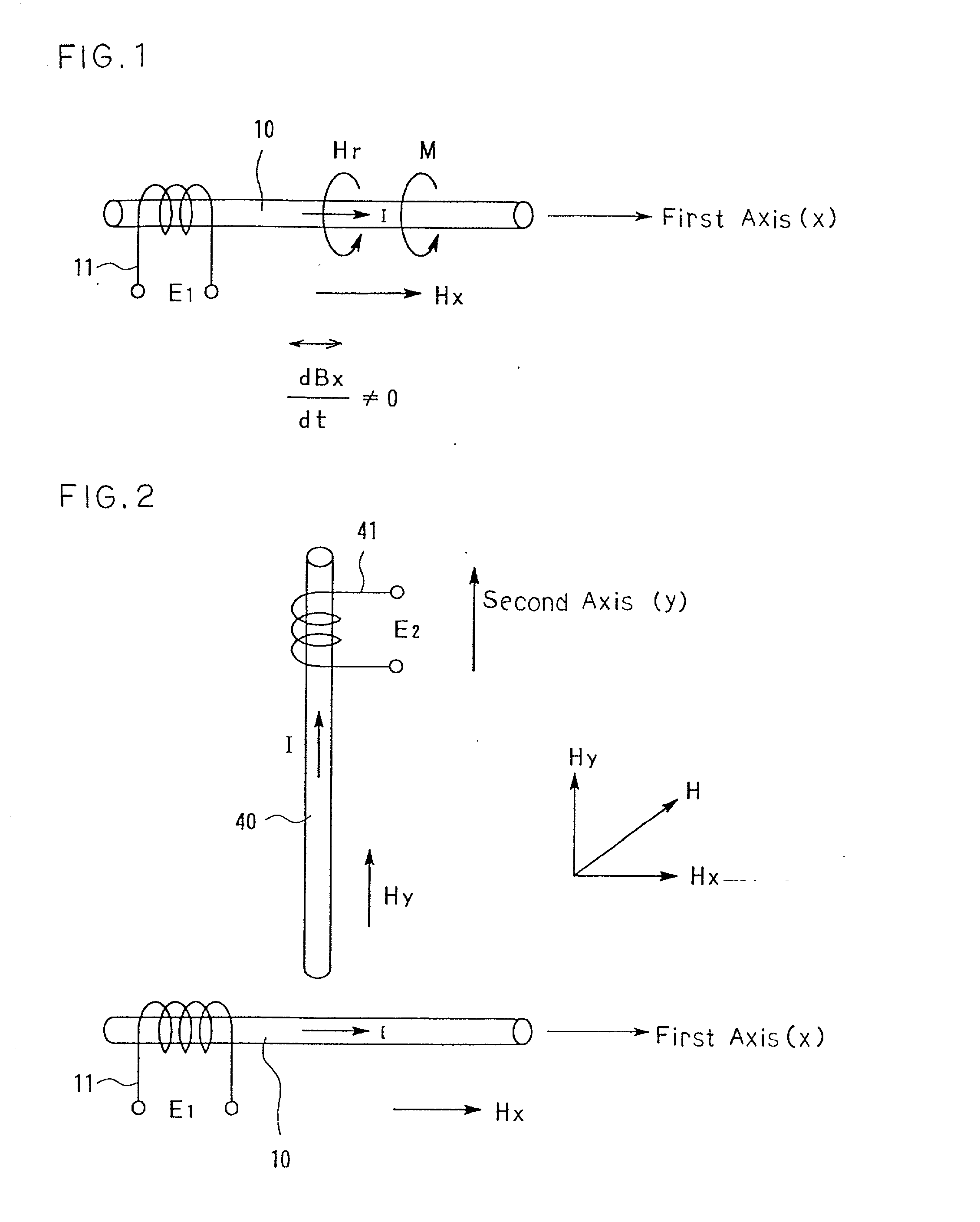
[0066] This is an explanation of the fundamental principles of the magnetic field detection of the present invention. FIG. 1 shows these principles. The electric current I is run through the wire-shaped first magneto-sensitive element 10 in the first axial (x axis) direction. By doing so, the magnetic field H.sub.r is generated in the circuital direction, that is in the direction perpendicular .omega. the current. The magnetic moment M of the first magneto-sensitive element 10 is also arranged in the circuital direction by the magnetic field H.sub.r. If the current I is an alternating current with frequency .omega., the magnetic field H.sub.r oscillates at the frequency.omega., and the magnetic moment M also oscillates at the frequency.omega.. Under the conditions where this AC current I is run, a static or alternating external magnetic field H.sub.x, which has a sufficiently low frequency, is applied. With this,...


PUM


Abstract

A magnetic field detection device that detects two components of an external magnetic field. The device uses the magneto-impedance effect in ferromagnetic amorphous wire. A detection coil wrapped around the amorphous wire detects the magnetic flux change of the amorphous wire, which is proportional to the external magnetic field. The sensitivity of the device is increased due to circuitry that extracts the initial output pulse. It is also increased with the use of negative feedback and with the comparison of differential outputs. The two sets of detection elements are placed orthogonally for greatest sensitivity. Resin molding is employed for easy handling. This detection device can be used as part of a compass.

Description

[0001] The present invention relates to a supersensitive magnetic field detection device. In general, the present invention is a device that can detect two components of any magnetic field vector. Specifically with respect to the detection of terrestrial magnetism, the present invention can be employed as part of a compass. As a concrete example of a practical application, it can be employed as part of a device which detects the position or direction of movement of an automobile.DESCRIPTION OF THE PRIOR ART[0002] As described in a previous patent, the inventor discovered the phenomenon where, when a high frequency (HF) electric current greater than 200 KHz is run (passed) through an ferromagnetic amorphous metal wire on the order of 50 .mu.m in diameter, there is a large change in the impedance of the above-mentioned wire in response to the external magnetic field component parallel to the wire. The phenomenon is called the magneto-impedance effect. Using this principle, a miniature...

Claims


Application Information

Patent Timeline
Patent Type & Authority Applications(United States)
IPC IPC(8): G01R31/02G01C17/30G01R33/02
CPCG01R33/02
Inventor HONKURA, YOSHINOBUYAMAMOTO, MICHIHARUMOURI, KANEO
Owner JAPAN SCI & TECH 33 3 0 0
Why Eureka
Try Eureka