Automatic optimizing pump and sensor system

a sensor system and automatic optimization technology, applied in the direction of machines/engines, pump control, positive displacement liquid engines, etc., can solve the problems of not being able to teach the use of signals, not being able to teach the operation frequency adjustment, and not being able to teach manual control or automatic control, etc., to achieve easy installation, de-installation, transport

Inactive Publication Date: 2001-10-25
HUMPHERIES JAMES C
View PDF0 Cites 55 Cited by
  • Summary
  • Abstract
  • Description
  • Claims
  • Application Information

AI Technical Summary

Benefits of technology

0038] 11. Another objective of this invention is that it be easy to install, de-install, transport and store.

Problems solved by technology

In this way the volume of delivered gas or liquid can be "adjusted" but is not manually controlled for optimum pumping efficiency or automatically controlled for optimum pumping efficiency or for varying load conditions.
Morita also does not teach a signal is produced by the motion of the ferromagnetic armature near the electromagnet.
Morita also does not teach how to adjust the operating frequency to match the pump self-resonant frequency.
Nor does Morita does teach the electromagnet operating current is adjusted manually or automatically to control flow or to minimize the operating power level for a given flow rate.
Morita also does not teach the use of any signal which is analyzed and used to provide control to optimize the operating frequency to deliver the maximum flow for a given operating power level.
Morita also does not teach the generation of a signal by the motion of the ferromagnetic armature near the electromagnet poles.
Hence, the armature would not exhibit "magnetism" per se with its own "permanent" magnetic field and would not be capable of inducing a voltage in the electromagnet coil.
Morita also does not teach that any signal that is generated and used to provide feedback for optimizing control of the pump.
Optimizing flow for a given operating power level would be antithetical to the control objectives for such a system--the outcome could be fatal.
The design is inherently insensitive to such influences because the moment of the plunger / tubing system is made very small such that the pump mechanism motor torque is relatively unaffected by such influences.
Because of mechanical design and control objectives, it is difficult to frame an argument for Tune's pump as having a varying self-resonance that is dependent on the pumping conditions.
They also do not teach interrupting the drive current to create an opportunity (in the interval when the drive current is off) to monitor the voltage produced in the electromagnet coil by the returning motion of the magnet near the core poles.
Furthermore Enomoto and Point & Hase do not teach interrupting the drive current to create an opportunity (in the interval when the drive current is off) to monitor the voltage produced in the electromagnet coil by the returning motion of the magnet near the core poles.
Enomoto also does not teach control of the drive frequency to optimize pumping efficiency for varying pumping loads.
Sipin does not teach a system for optimizing flow rate for a given pump drive current.
O'Dougherty does not teach a pump and a flow measuring device configured for automatic control of flow rate or for automatic optimization of pumping efficiency with varying pumping loads.
As claimed, O'Dougherty's flow analyzer has no means for deriving a signal that could be used in an automatic control system.
Unfortunately none of the prior art devices singly or even in combination provide all of the features and objectives established by the inventor for this system as enumerated below.

Method used


Image

  • Automatic optimizing pump and sensor system
  • Automatic optimizing pump and sensor system
  • Automatic optimizing pump and sensor system

Examples


Embodiment Construction

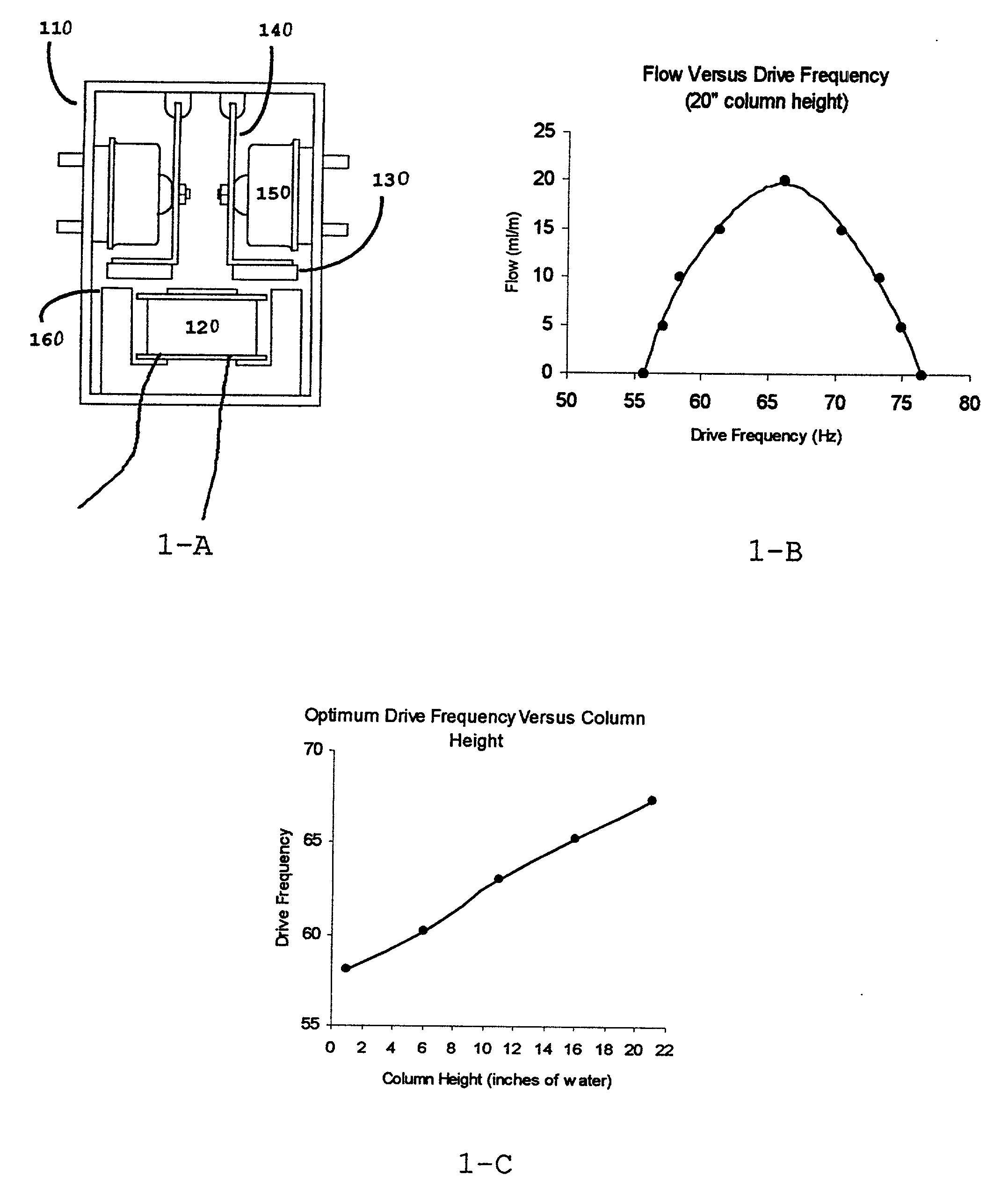
[0096] The preferred embodiment of the invention includes a reciprocating electromagnetic pump mechanism comprising one or more arms with magnet(s) attached to one end of the arm(s) such that the arm(s) may be vibrated under the influence of an electromagnetic field, that field being produced by the periodic flow of current in a coil wound about a bipolar or tripolar core. The vibration of the arm(s) being mechanically coupled to diaphragm(s) incorporating valves and ports such that a vacuum is created at one port and, simultaneously, a pressure is created at another port. The time the current flows through the coil is made to be short so that the magnets are impelled during either the vacuum or pressure stroke but are not impelled during the reciprocal stroke, the reciprocal stroke being completed by the spring energy stored in the arm / magnet / diaphragm system

[0097] During the reciprocal stroke the motion of the magnet(s) near the core induces a voltage in the coil that is proportio...


PUM


Abstract

A reciprocating electromagnetic pump comprising a coil wound about a bipolar or tripolar core, a diaphragm structure mechanically coupled to at least one arm with a magnet attached to one end of the arm and a controller electronically connected to the coil. The arm is vibrated under the influence of a periodic electromagnetic field to produce flow. The flow of current through the electromagnet is interrupted so that the magnets are impelled during either a vacuum or a pressure stroke, but are not impelled during the reciprocal stroke. A microprocessor houses the controller which analyzes amplitude and frequency components of a signal produced in the electromagnet coil during the reciprocal stroke to provide a pump flow rate, a pumping efficiency, a pumping load and a height of the fluid column into which the pump mechanism is operating. The controller employs automatic feedback such that an operating frequency is controlled to match a self-resonant frequency of the pump and a coil current is controlled to a minimum value required to provide the desired flow. The microprocessor further comprises a pulse generator and a solid state switch that interrupts current flow through a pump electromagnet.

Description

[0001] This application is continuation-in-part application to Ser. No. 09 / 272,935 filed by the same inventor on Mar. 20, 1999 then entitled "A Self Optimizing Pump / Sensor System" which application claims the benefit of Provisional Application Number 60 / 078,743 that was filed on Mar. 20, 1998[0002] This invention relates to method devices and system for fludic pumps. More particularly it pertains to / gas pumps, gas flow control and fluid level sensing. This invention optimizes the efficiency of electromagnetic reciprocating pumps such as those described in U.S. Pat. No. 4,154,559, U.S. Pat. No. 4,170,439, and U.S. Pat. No. 5,052,904 (among others) by control of the pump driving frequency and drive current. Energy savings are realized in the pump operation by eliminating off-nominal pump drive conditions. In practice, electromagnetic reciprocating pumps are driven by the continuous 60 Hz sinusoidal AC service available from utility power companies (50 Hz in some countries other than ...

Claims


Application Information

Patent Timeline
Patent Type & Authority Applications(United States)
IPC IPC(8): F04B17/04F04B43/00F04B43/04
CPCF04B17/04F04B43/0081F04B43/04
Inventor HUMPHERIES, JAMES C.
Owner HUMPHERIES JAMES C
Why Eureka
Try Eureka