Non-dispersive infrared cell for gas analysis

a gas analysis and infrared cell technology, applied in material analysis, radiation pyrometry, instruments, etc., can solve the problems of loss of energy, increased cost owing to complex structure, and all the energy emitted into the optical field

Inactive Publication Date: 2001-12-06
BRUNAMOTI MASSIMO +2
View PDF0 Cites 37 Cited by
  • Summary
  • Abstract
  • Description
  • Claims
  • Application Information

AI Technical Summary

Problems solved by technology

This causes that, unavoidably, not all the energy emitted enters the optical path, with a subsequent loss of energy.
The need of three distinct units causes additional costs owing to the complex structure.
the assembling and final inspecting costs.
As a consequence, the apparatus is more cumbersome.
These devices make more complicated the structure of the apparatus and of the gas path.
This causes that only a fraction of the global energy is detected by each element of the sensor, with a loss of ratio measured signal / noise (S / N).

Method used


Image

  • Non-dispersive infrared cell for gas analysis
  • Non-dispersive infrared cell for gas analysis
  • Non-dispersive infrared cell for gas analysis

Examples


Embodiment Construction

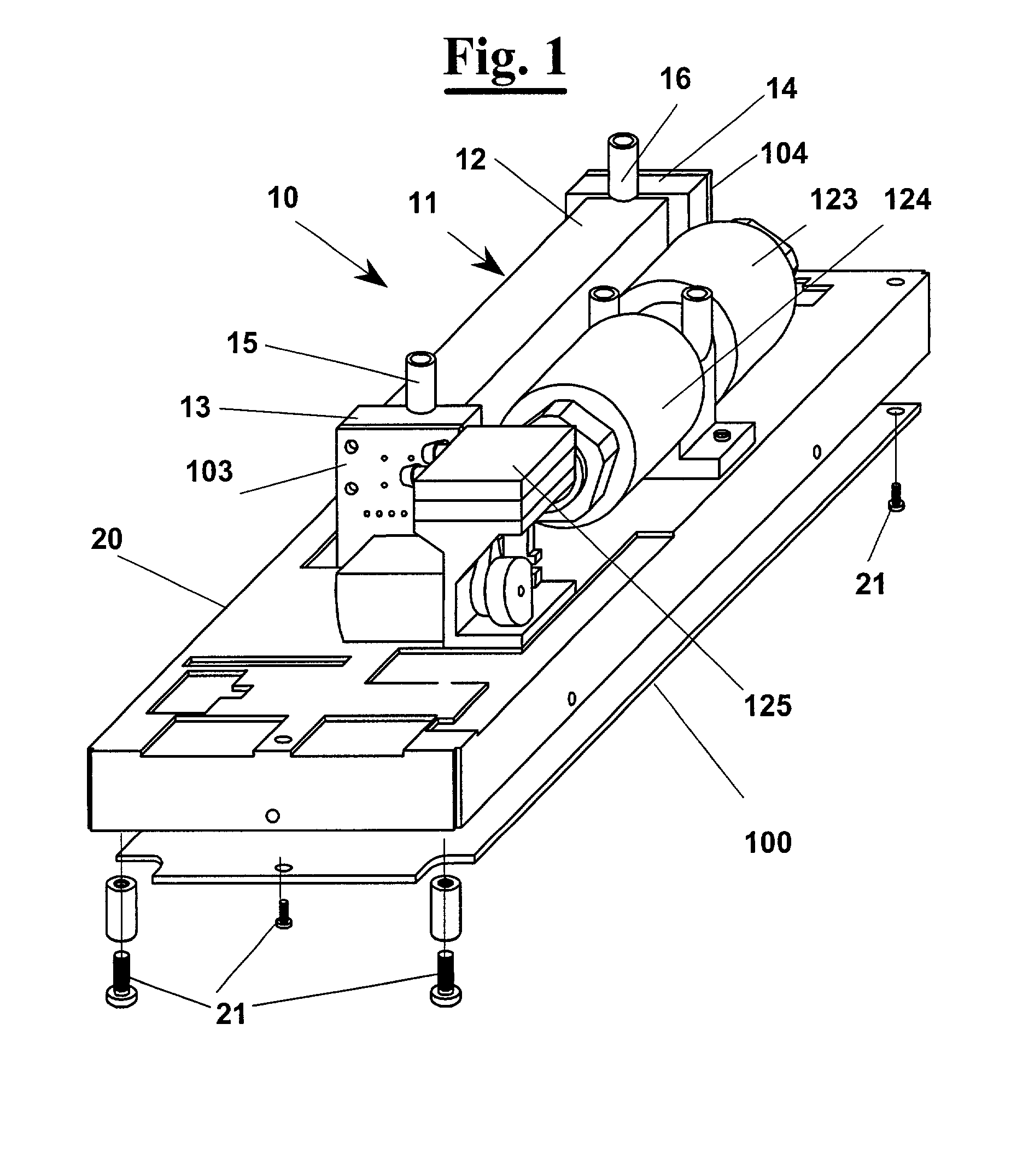
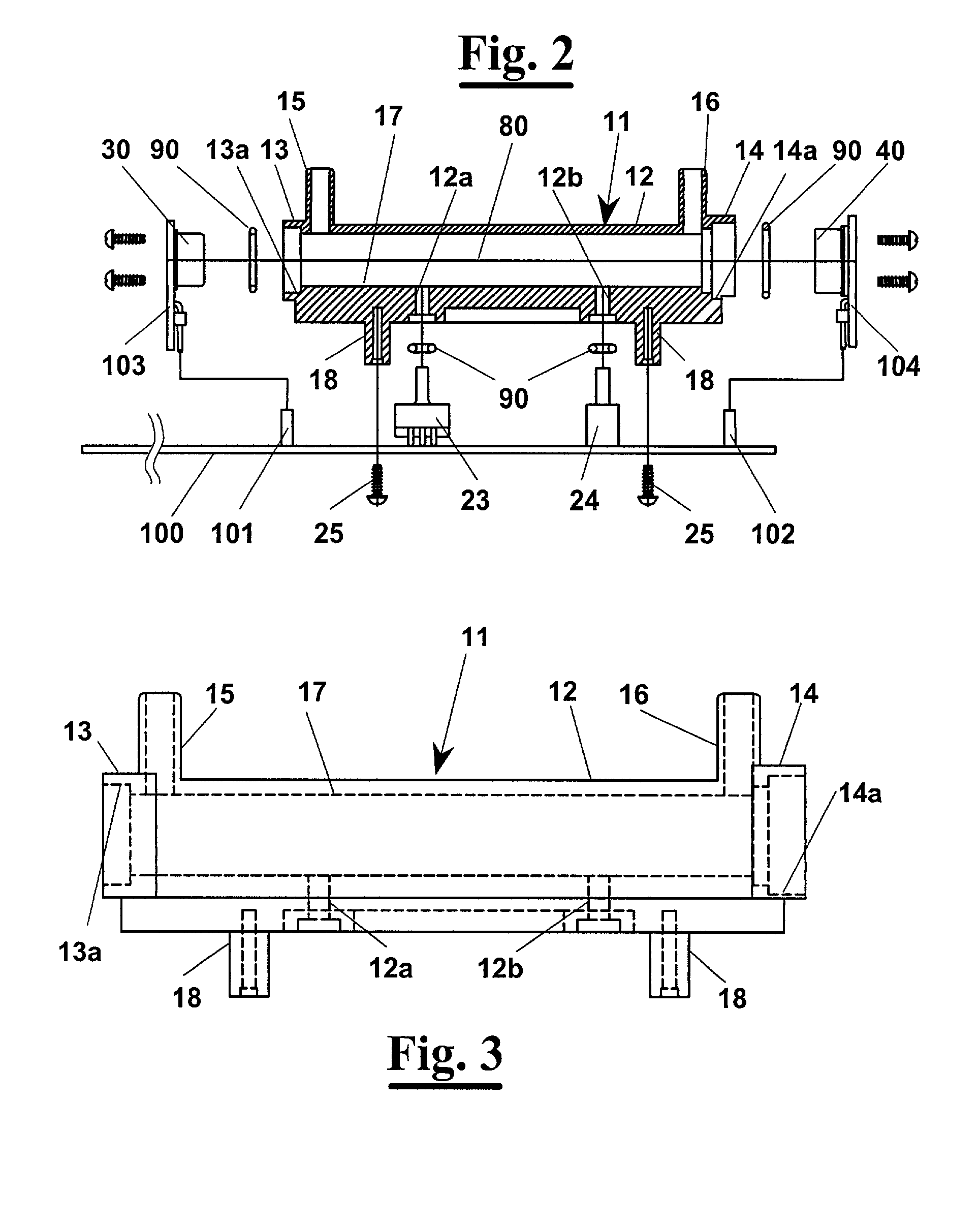
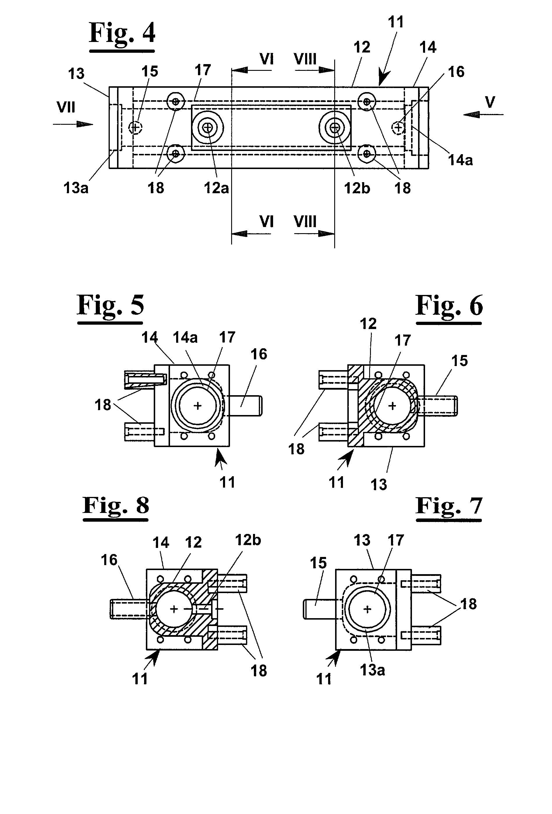
[0046] With reference to FIG. 1, a NDIR gas analyser according to the invention has a gas containing cell 10, comprising an elongated hollow body 11, having a central portion 12 and two end portions 13 and 14.

[0047] The two end portions have respectively ducts 15 and 16 of inlet and outlet of the gas to analyse that are integrated in elongated body 11 of the cell and precisely at the two end portions 13 and 14. Ducts 15 and 16 have protruding terminals for fastening inlet and outlet rubber tubes not shown of the gas to analyse.

[0048] Cell 10 is mounted, through a shielding box 20, directly on a printed circuit board 100 comprising all the electronic control units of the analyser. Box 20, which is connected to board 100 by means of screws 21, holds electrochemical sensors 123 and 124 respectively for measure of oxygen and of nitrogen oxides, or equivalent electrochemical sensors for other gases. Furthermore, it comprises a pump 125 and other set instruments.

[0049] End portions 13 and...


PUM

PropertyMeasurementUnit
transmissionaaaaaaaaaa
pressureaaaaaaaaaa
temperatureaaaaaaaaaa

Abstract

A method non-dispersive infrared (NDIR) gas analysis, which can be carried out by a gas analyser comprising a cell (10) containing of gas, a sender (30) of IR waves and at least a receiver (40) of such waves. The transmission of IR waves and/or the reception of IR waves after the passage of the gas occur directly in the cell (10) same wherein the gas is fed. The analyser has a body (11) defining the cell (10), a sender (30) of IR waves and at least a receiver (40) of such waves, that are located opposite to each other with respect to the cell (10). The IR sender (30) and the receiver (40) are both arranged in the cell (10) at its end (13,14). The body (11) has inlet (15) and outlet (16) channels for the gas and a cavity (17), which can be metal coated inside and that defines the optical path (80) for the IR waves. The body (11) is directly mounted on a printed circuit board (100) that has the electronic control unit for transmission of the IR waves and for analysis of the signals coming from the receiver (40).

Description

DESCRIPTION[0001] 1. Field of the Invention[0002] The present invention relates to an infrared (IR) gas analyser. More precisely, it relates to a NDIR (Non-Dispersive Infrared) analyser of several gases.[0003] 2. Background of the Invention[0004] The analysers of NDIR type are well known in the art. All of them are based on the principle of attenuation of the infrared waves (IR) that cross a gas, with respect to that attenuated without gas. The concentration of gas present in the sample analysed is therefore evaluated from this comparison.[0005] The existing analysers provide, typically, a sender of waves, a cell or chamber wherein the gas to analyse flows, and a sensor receiver. The sender and the receiver are external to the cell, which normally is a tubular chamber with transparent ends for passage of the IR waves. The cell, therefore, defines an optical path crossed by the waves coming from the IR sender, which usually is an heated element. The infrared waves, after having cross...

Claims


Application Information

Patent Timeline
Patent Type & Authority Applications(United States)
IPC IPC(8): G01N21/3504G01N21/61
CPCG01N21/3504G01N21/61
Inventor BRUNAMOTI, MASSIMOMARCHI, FERRUCCIOTOSI, STEFANO
Owner BRUNAMOTI MASSIMO
Why Eureka
Try Eureka