Aircraft fuselage shell component with crack propagation resistance

a fuselage shell and crack-propagating technology, which is applied in the field of aircraft fuselage shell construction, can solve the problems of failure of respective stiffening profile members, increased costs and efforts in fabrication procedures, and large total weigh

Inactive Publication Date: 2002-01-03
AIRBUS OPERATIONS GMBH
View PDF0 Cites 26 Cited by
  • Summary
  • Abstract
  • Description
  • Claims
  • Application Information

AI Technical Summary

Problems solved by technology

Such a joining method of the stiffening profile members onto the skin sheets is disadvantageous in comparison to laser welding, because the riveting and adhesive bonding result in a greater total weight, and involve greater costs and efforts in the fabrication procedures.
Particularly, with a riveted or adhesively bonded junction between the skin sheets and the stiffening profile members, a crack that initiates in the skin sheet and progresses to a location of a stiffening profile member will generally not propagate into the stiffening profile member itself, because the rivets or adhesives do not provide the necessary degree of local force coupling to transmit the crack into the stringer or frame member.
The respective stiffening profile member is able to maintain this condition for a certain number of load alternations, until the extra loading transmitted from the skin into the stiffening profile member eventually fatigues and overloads the profile member, leading to a failure of the respective stiffening profile member.
At that point, the fuselage skin and the affected stiffening profile member will fail, typically in a sudden rupturing manner, which leads to a failure of the fuselage shell structure.
As a result, any crack in the skin sheet will readily propagate through the stringers and frame members as well, which leads to a significantly lower residual or remaining strength of the overall fuselage shell structure upon the occurrence of such a crack.
Namely, once such crack forms, it will readily propagate through both the skin and the stiffening profile members, and there is no structural component remaining to hold together the fuselage shell at the location of the crack, thus leading to a failure of the overall shell structure.
These areas especially include the sides and the upper or top portion of the fuselage, since these areas are especially subjected to tension loads during operation, with a consequent tendency toward crack opening and propagation.
Such thickening of the fuselage shell in these areas would, however, lead to an unacceptable increase in the overall weight of the fuselage.

Method used


Image

  • Aircraft fuselage shell component with crack propagation resistance
  • Aircraft fuselage shell component with crack propagation resistance
  • Aircraft fuselage shell component with crack propagation resistance

Examples


Embodiment Construction

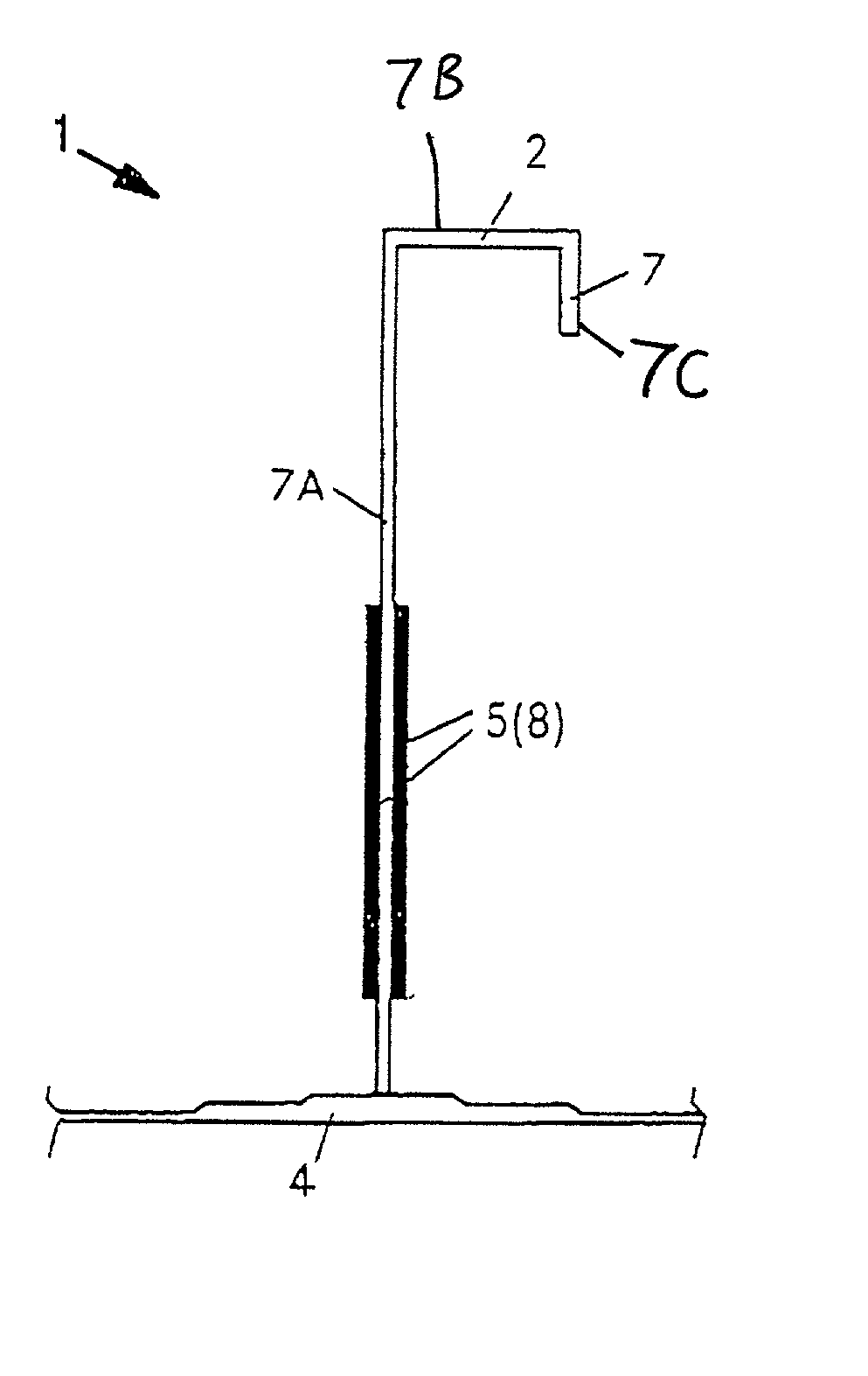
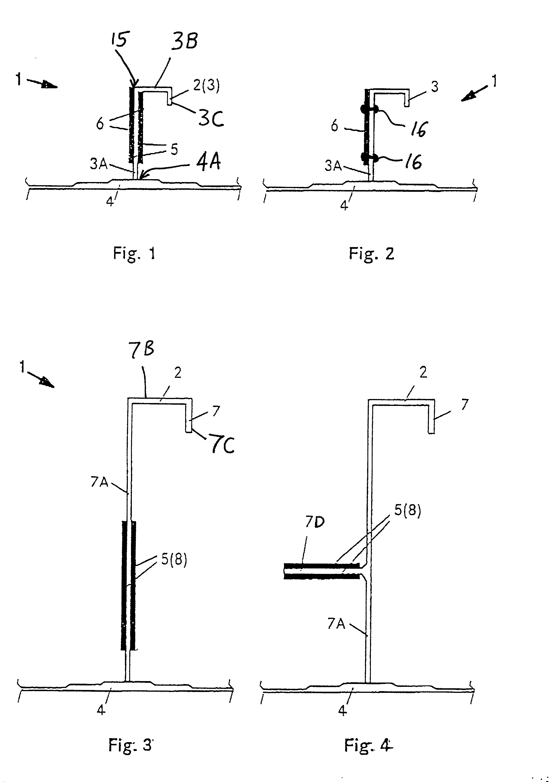
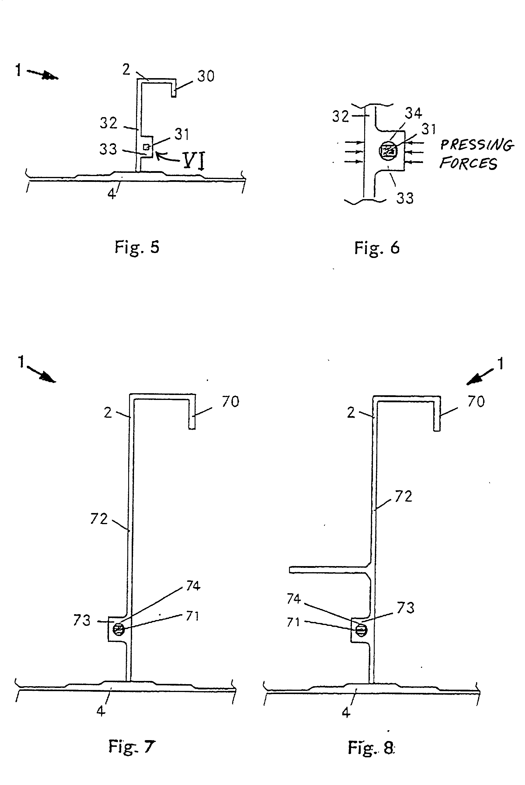
[0029] FIGS. 1 and 2 each respectively show a portion of a structural shell component and particularly a fuselage shell component 1 in the area at which a stiffening profile member 2 is welded onto a fuselage skin sheet 4. Particularly in FIGS. 1 and 2, the stiffening profile member 2 is a stringer 3 that runs in the aircraft longitudinal direction of the aircraft fuselage structure. The overall structural shell component 1 to be used as a fuselage shell of an aircraft includes a plurality of such stringers 3 respectively extending in the aircraft longitudinal direction and spaced apart from one another in the aircraft circumferential direction. Generally, the stiffening profile members 2 could be stringers, frame members, ribs, spars, etc.

[0030] The connection between each stringer 3 and the skin sheet 4 is achieved by means of welding, such as laser beam welding, or according to any other conventionally known technique, for example as disclosed in the German Patent Publications 19...


PUM

PropertyMeasurementUnit
strengthaaaaaaaaaa
tensionaaaaaaaaaa
lengthsaaaaaaaaaa

Abstract

When stiffening members, such as stringers and frame members, are welded onto a skin sheet to form an aircraft fuselage shell, a crack originating in the skin sheet tends to propagate through the weld joints into the stiffening members. In order to prevent crack propagation into a stiffening member, the stiffening member is reinforced with a web doubler plate or a tension band made of high strength steel or titanium alloys or fiber-reinforced composites. The doubler plate is riveted or adhesively bonded onto a stiffening member web, or the tension band is crimped into the stiffening member web. The resulting fuselage shell structure has crack stopping properties and thus an increased residual strength, so it can be used with welded joints at all areas of the fuselage shell, including the top and sides as well as the bottom of the fuselage.

Description

PRIORITY CLAIM[0001] This application is based on and claims the priority under 35 U.S.C. .sctn.119 of German Patent Application 100 31 510.0, filed on Jun. 28, 2000, the entire disclosure of which is incorporated herein by reference.[0002] The invention relates to a structural component and particularly a fuselage shell component for an aircraft, including a skin sheet and several stiffening profile members connected to the skin sheet at least partially by welding.BACKGROUND INFORMATION[0003] In the construction of aircraft fuselages, it has become known to connect the stiffening profile members, such as frame members and stringers, to the outer fuselage skin by means of welding, at least partially or at certain locations of the aircraft. For example, see German Patent Publication DE 196 39 667 and corresponding U.S. Pat. No. 5,841,098, or German Patent Publication DE 198 44 035. Particularly, the stringers and frame members are welded onto large format skin sheets by means of lase...

Claims


Application Information

Patent Timeline
Patent Type & Authority Applications(United States)
IPC IPC(8): B23K31/02B64C1/12B64C1/08
CPCB23K31/02B64C1/12B64C1/08
Inventor SCHMIDT, HANS-JUERGEN
Owner AIRBUS OPERATIONS GMBH
Why Eureka
Try Eureka