Electromagnetic device with embedded windings and method for its manufacture

a technology of embedded windings and electromagnetic devices, which is applied in the manufacture of stators/rotors, magnetic circuit shapes/forms/construction, generators/motors, etc., can solve the problems of affecting the electromagnetic characteristics of stators, affecting the efficiency of manufacturing, and scrap steel pieces, which are often not used productively by manufacturers

Inactive Publication Date: 2002-01-17
REMY TECHNOLOGIES LLC
View PDF0 Cites 3 Cited by
  • Summary
  • Abstract
  • Description
  • Claims
  • Application Information

AI Technical Summary

Benefits of technology

[0011] Stator windings are conventionally produced from an insulated electrical conductor of types known in the art including, for example, insulated single strand copper wire. The insulated electrical conductor is conventionally formed by methods known in the art into substantially cylindrical winding configurations which will fit within the slots in the stator core, and which will produce the desired electrical effect when the windings are placed in a moving magnetic field, or the desired magnetic effect when the windings are energized with an electric current. The windings are inserted into slots in the stator to maximize the electromagnetic coupling between the windings and the flux path, and to minimize the air gap between the rotor and stator. The portion of the windings which is aligned parallel to the axial direction of the core is conventionally known as the "active portion" of the windings. The portions of the windings which resides outside the stator core at each axial end of the stator core, and which function to conduct electricity from the active portion of the windings which resides in a first slot to the active portion of the windings which resides in a second slot, are conventionally known as the "end turns."
[0015] The magnetic loading of the stator core may be increased without increasing the stator dimensions by fabricating the stator core from a material known in the art to have a higher saturation flux density than steel, such as, for example, an alloy of neodymium iron boron. Such materials improve magnetic loading, but at a substantially higher cost. It is desired to have a stator core fabricated from a readily available, low cost, magnetic material, wherein a higher degree of magnetic loading may be achieved without a corresponding increase in stator size.
[0017] It is known in the art that the total current carried in the stator slots, and therefore the conductor packing factor, is limited by the need to dissipate the heat generated by electrical resistance in the conductors. The heat must be dissipated either through the stator core, or through the conductors themselves to the end turns of the conductors. The non-reactive, non-conducting material used to fill the stator slots substantially thermally isolates the conductors from the stator core. As a result, most of the heat must be dissipated through the end turns. The total current carried in the stator slots, and therefore the conductor packing factor, can be significantly increased by providing a direct cooling path through the stator core.
[0029] The present invention is a novel powdered magnetic material electromagnetic device with embedded windings, and a novel method for its manufacture. In one embodiment, the electromagnetic device is a stator. The windings comprise preformed insulated electrical conductors, as are common in prior art electromagnetic device designs. The windings are placed into a compaction die cavity, and the remaining volume of the compaction die is filled with a quantity of powdered magnetic material which is sufficient to fully surround and encapsulate the windings after compaction. Radial compaction is used to compact the powdered magnetic material into a solid magnetic structure with the preformed windings embedded therein. Radial compaction avoids or reduces distortion of the windings during compaction. Radial compaction by the dynamic magnetic compaction method has been found to produce a suitable result. An electromagnetic device with embedded windings according to the present invention will be of sufficient density and physical strength to be a substitute for prior art devices in a variety of applications including, for example, vehicular alternator applications. By embedding the windings within the core, an electromagnetic device according to the present invention may be smaller and of a lesser mass than a prior art device offering similar performance.

Problems solved by technology

Such movement, if permitted, could damage the electrical insulation on the stator windings, and / or could alter the electromagnetic characteristics of the stator.
The process of punching the steel laminations from the sheet steel creates scrap steel pieces, which often cannot be used productively by the manufacturer.
In addition to the cost of the wasted sheet steel pieces, often the manufacturer must incur additional expense involved with the disposal of the wasted sheet steel pieces.
Finally, the process of producing the finished stator core from the raw sheet steel is a multiple step process requiring expensive material handling to be performed during and / or between each process step.
The stator core of Ward et al. does not overcome all disadvantages of a prior art stator core made with steel laminations.
A disadvantage present in prior art stator design using internally slotted stator cores, is that the slots reduce the internal surface area of the stator adjacent to the rotating rotor, thereby reducing the ability for magnetic flux to flow between the stator and the rotor.
Such materials improve magnetic loading, but at a substantially higher cost.
Another disadvantage of the prior art stator designs arises from limitations on the amount of electrical current which can be carried in the stator windings installed in a stator slot.
Another disadvantage of the prior art stator designs arises from the significant contribution to stator size made by the end turns of the windings.
The mold is opened destructively to reveal a rotor core with embedded rotor windings.

Method used


Image

  • Electromagnetic device with embedded windings and method for its manufacture
  • Electromagnetic device with embedded windings and method for its manufacture
  • Electromagnetic device with embedded windings and method for its manufacture

Examples


Embodiment Construction

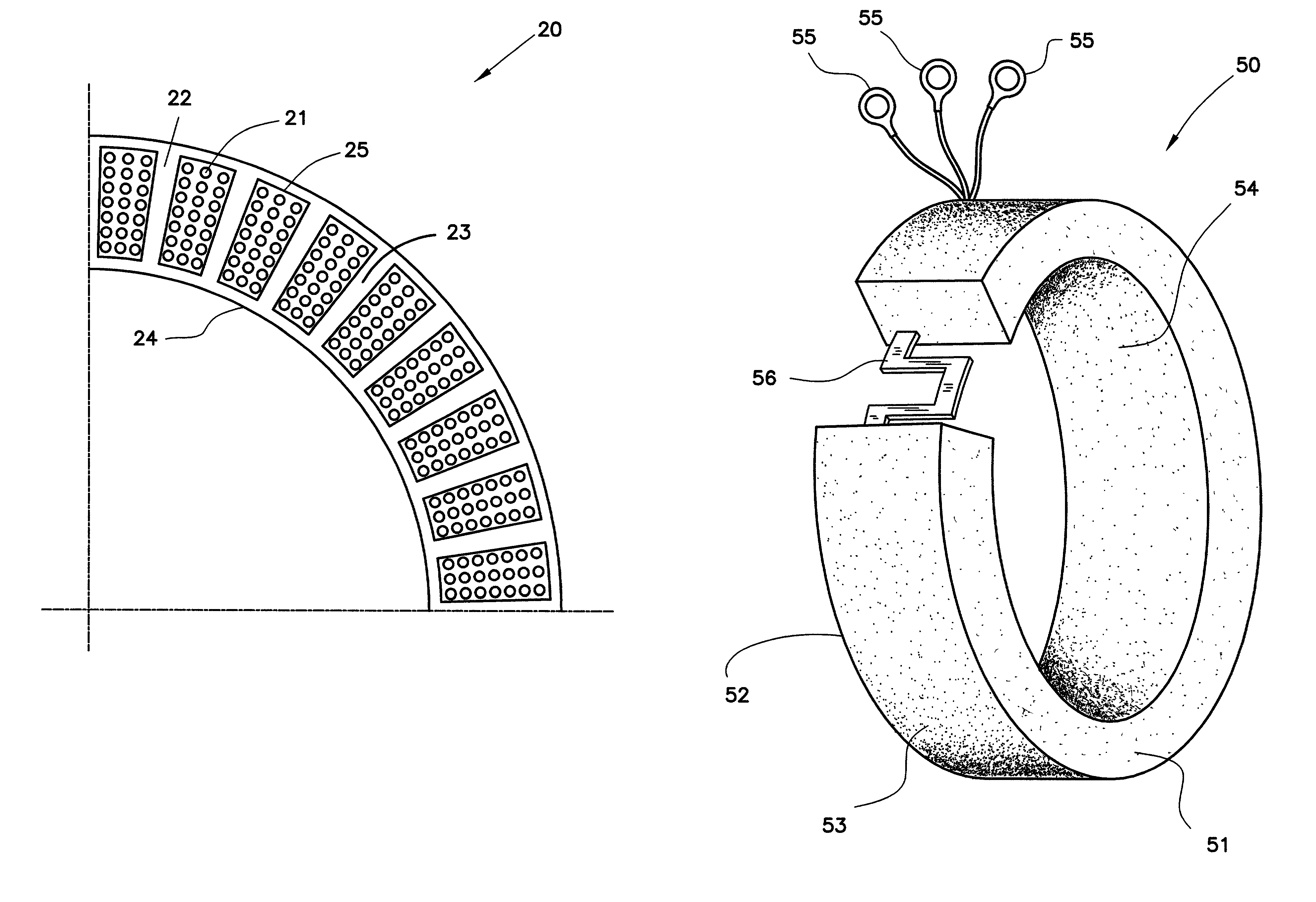
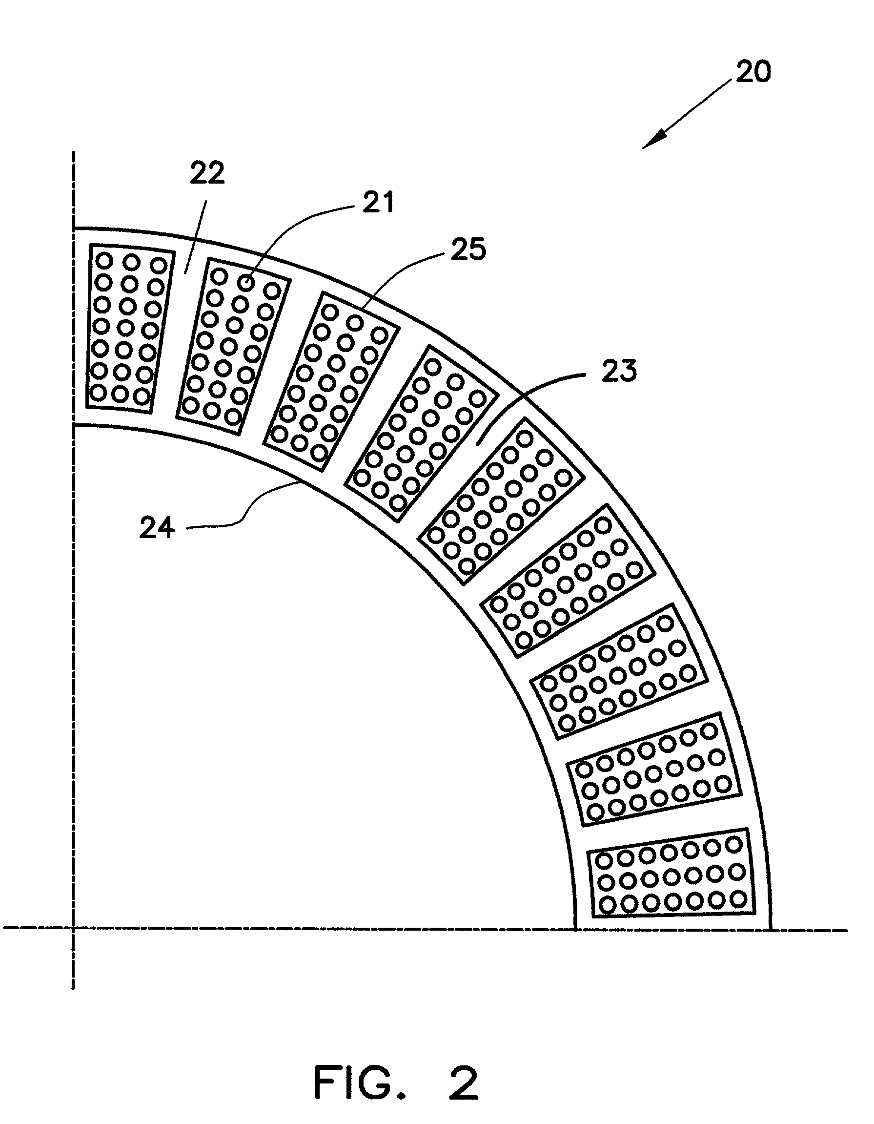
[0036] The present invention is a novel method for manufacturing a stator core from powdered magnetic material, and embedding stator windings within the stator core, and a novel powdered magnetic material stator core with embedded stator windings produced by the method.

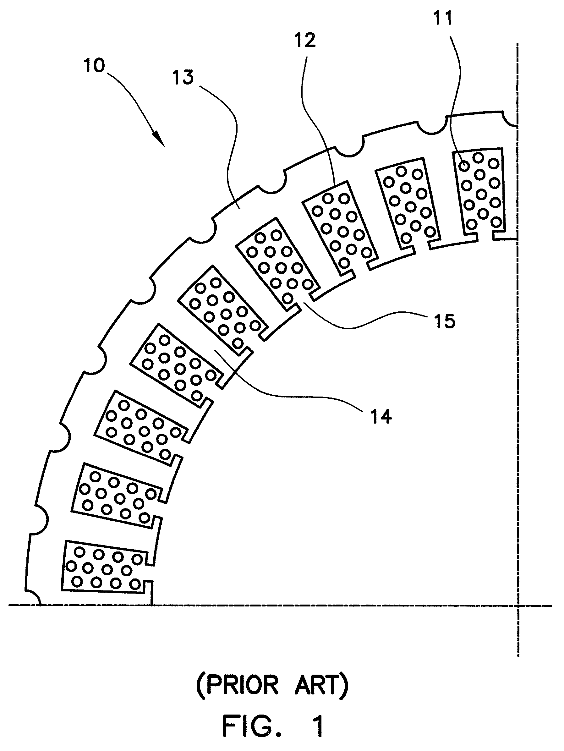
[0037] To better illustrate the advantages of the present invention, it is useful to examine a stator made according to the prior art methods. FIG. 1 shows one-quarter of a cross-section of such a prior art stator. In FIG. 1, stator 10 is shown with a plurality of windings 11 installed in a plurality of slots 12. Stator core 13 is fabricated from a plurality of stacked steel laminations (only the top lamination being shown in FIG. 1). Stator core 13 includes a plurality of teeth 14 which define the slots 12. Windings 11 were shaped into the desired configuration prior to installation into stator core 13. During installation into stator core 13, windings 11 were inserted into slots 12 through slot openings 15.

[0038] FI...


PUM

PropertyMeasurementUnit
saturation flux densityaaaaaaaaaa
shrinkageaaaaaaaaaa

Abstract

A powdered magnetic material stator core with embedded stator windings and a method for its manufacture. Embedding the windings within a radially compacted powdered magnetic material stator core enables equivalent or better electromagnetic performance in a significantly reduced size. Radial compaction of the powdered magnetic material minimizes the distortion of the stator windings during compaction.

Description

[0001] 1. Field of the Invention[0002] This invention relates to the field of electromagnetic device design and manufacturing.[0003] 2. Description of the Prior Art[0004] An electromagnetic device, such as an electric motor or an electric generator, contains two electromagnetic components: a stationary component known as a "stator," and a rotating component known as a "rotor." In the most common embodiment, the rotor and the stator are cylindrical in shape. The cylindrical rotor is installed inside the hollow, cylindrical stator in such a way that when the rotor rotates, the outer surface of the rotor is proximate to, but does not touch, the inner surface of the stator. The space between the outer surface of the rotor and the inner surface of the stator is known as the "air gap."[0005] It is known in the art that a stator and a rotor each may be manufactured from a core made from a magnetic material, around which or within which insulated electrical conductors known as "windings" ar...

Claims


Application Information

Patent Timeline
Patent Type & Authority Applications(United States)
IPC IPC(8): H02K1/12H02K3/04H02K15/02H02K15/06
CPCH02K1/12Y10T29/49009H02K15/02H02K3/04
Inventor JOHNSTON, RALPHCHO, CHAHEE PETERMARTIN, RONALD A.
Owner REMY TECHNOLOGIES LLC
Why Eureka
Try Eureka