Gas discharge tube

Inactive Publication Date: 2002-01-31
HAMAMATSU PHOTONICS KK
View PDF0 Cites 5 Cited by
  • Summary
  • Abstract
  • Description
  • Claims
  • Application Information

AI Technical Summary

Benefits of technology

[0010] The focusing opening is preferably formed so that B / A is in a range of 0.1 to 0.25 and the opening area is in a range of 0.15 to 0.25 mm.sup.2. This permits the discharge tube to supply light with uniform luminance distribution and with extremely high luminance, thereby enhancing the intensity of the spot emission so as to meet market needs.

Problems solved by technology

In the conventional gas discharge tube, however, since the focusing opening of the small hole had the size of 0.4 mm horizontal and 2.5 mm vertical, there arose the problem that it was hard to obtain a beam with high luminance and in uniform slit shape though it was easy to induce arc discharge.
This is because decrease of the diameter of the focusing opening to below 0.5 mm will result in increasing the barrier between the hot cathode and the anode and thus necessitating high energy for a start of discharge.
With increase in this energy (for example, with increase in discharge voltage), there will occur an event of failure in lighting of the gas discharge tube because of the abnormal discharge.

Method used


Image

  • Gas discharge tube
  • Gas discharge tube
  • Gas discharge tube

Examples


Embodiment Construction

[0025] The preferred embodiments of the gas discharge tube according to the present invention will be described hereinafter in detail with reference to the accompanying drawings.

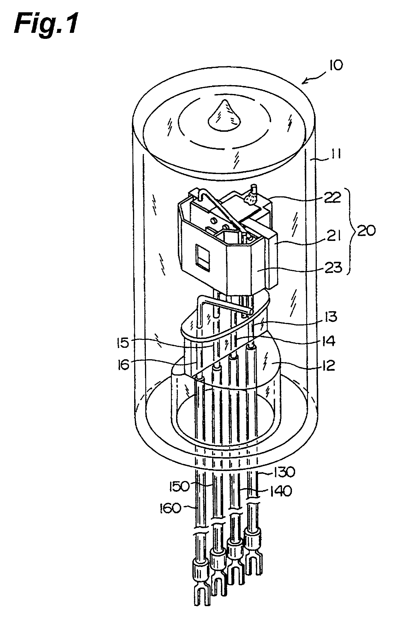
[0026] FIG. 1 shows a side-on type deuterium lamp as an example of the gas discharge tube. In this gas discharge tube 10, a light-emitting section 20 is housed inside an envelope 11 of glass and deuterium gas (not illustrated) is confined under the pressure of about several Torr. The envelope 11 is formed in a cylindrical shape with its head portion being sealed and the bottom portion of the envelope 11 is hermetically sealed by a glass stem 12. The envelope 11 is made of ultraviolet-transmitting glass or silica glass having a high UV transmittance.

[0027] Four lead pins 13 to 16 juxtaposed on a straight line extend from the bottom portion of the light-emitting section 20 and penetrate the stem 12. These lead pins 13 to 16 are covered by insulating members 130, 140, 150, 160, respectively, and connected to a ...


PUM


Abstract

In order to ensure high luminance while enabling lighting of a gas discharge tube, an opening area S of a focusing opening was narrowed down into a range of 0.15 to 0.5 mm2. In addition, in order to attain a uniform emission with high luminance, while taking the aforementioned opening area S into consideration, the inventor noted a relation between an opening length A in a longitudinal direction of the focusing opening and an opening length B thereof in a direction perpendicular to the longitudinal direction. Then the shape of the focusing opening was specified by use of an equation to define the relation of B / A and the value thereof was narrowed into a range of 0.1 to 0.5. By limiting the focusing opening by the various parameters in this way, the inventor succeeded in specifying uniform slit light with a good lighting property and with high luminance in the gas discharge tube.

Description

[0001] This is a Continuation-In-Part application of International Patent application serial No. PCT / JP99 / 06909 filed on Dec. 9, 1999, now pending.BACK GROUND OF THE INVENTION[0002] 1. Field of the Invention[0003] The present invention relates to a gas discharge tube and, more particularly, to a gas discharge tube used as an ultraviolet light source or the like for spectrophotometer, liquid chromatography, and so on.[0004] 2. Related Background Art[0005] The conventional technology in this field includes the technique disclosed in Japanese Patent Application Laid-Open No. H04-147557. In a deuterium discharge tube described in this application, a focusing opening as a small hole of slit shape is formed in a focusing electrode plate interposed between anode and cathode. This focusing opening is formed in such a strip shape as to match with a slit shape of an analyzer, thereby increasing utilization efficiency of light emitted from the discharge tube.[0006] In the conventional gas disc...

Claims


Application Information

Patent Timeline
IPC IPC(8): G01N21/01G01N21/33H01J61/10H01J61/68
CPCH01J61/10H01J61/68
Inventor IKEDO, TOMOYUKI
Owner HAMAMATSU PHOTONICS KK
Why Eureka
Try Eureka