Process for injection foaming, and machine and composition therefore

a technology which is applied in the field of injection foaming and composition processing, and can solve the problems of decomposition of part of the foaming agent, uneven foaming, and lower gas generation efficiency

Inactive Publication Date: 2002-02-14
MITSUI CHEM INC
View PDF4 Cites 58 Cited by
  • Summary
  • Abstract
  • Description
  • Claims
  • Application Information

AI Technical Summary

Problems solved by technology

However, when a chemical foaming agent is added to pellets, a relatively large amount such as 1 to 5 wt % of the chemical foaming agent is needed, and in addition, the foaming agent in power state and the pellets got separated, causing uneven foaming.
Besides, in the case of a chemical foaming agent being as a masterbatch, part of the foaming agent is decomposed due to the heat in the extruder when it is produced.
This causes a problem of lower efficiency in the generation of gas at the time of injection foaming.
On top of that, chemical foaming agents are expensive, and this is making the materials cost higher.
Besides, in some cases, decomposition residues of a chemical foaming agent remained in the cylinder of the injection molding machine for a long time and appeared on the surfaces of molded articles from time to time, spoiling their appearance.
On the other hand, in the case of the in-line-type injection molding method using a physical foaming agent in injection molding, it happens in some cases that even if a hole is made in the cylinder for the injection of the physical foaming agent, it cannot be injected into the cylinder, depending on the position of the screw, because the relationship between the position of the injection hole and that of the screw is not always constant unlike in the case of an extruder since the resin is plasticized, metered and injected as the screw moves forward and backward in the cylinder.
In this way, it has been much more difficult to feed a physical foaming agent to an injection molding machine than to an extruder.
This presents the problems of a possibility of the molded article being smeared with such discharged resin and a high rate of production of defective articles.
Furthermore, such injection molding method requires a system that will open and close the physical foaming agent injection hole made in the cylinder in response to the movement of the screw and will control the motion of the pressure pump, many sensors, and an information processing system; and as a result, such injection molding method becomes complex and expressive.
However, it is difficult to accomplish this with the mold clamping force of a common injection molding machine, and because of this, gas tightness so required is normally attained by use of a packing made of rubber or the like.
In spite of that, it has been difficult to produce a large volume of products because such packing slowly becomes worn out as the cavity is heated.
Moreover, since the degree of the gas tightness of the cavity is raised, there has been a possibility that the counter-pressurizing gas is not released from the cavity at the time of injection with the result that there will be a gas holdup in the cavity, causing a dent in molded articles and consequently a decline in their appearance.
Injection of a physical foaming agent under high pressure will require a pressure pump and complex and expressive equipment.
It is difficult to impregnate the resin with a physical foaming agent at a temperature in the vicinity of room temperature in a short time, and such method is not suitable for industrial continuous production.
According to this method, there is no need to conduct the injection of a physical foaming agent in synchronization with the motion of the mold and the screw, but since a pump is used for the purpose of pressurization, the manufacturing equipment becomes expensive.
In addition, since the yield of the materials declines as the melted resin is discharged out of the system, the application of the method to the manufacture of inexpensive foam products has been difficult.

Method used


Image

  • Process for injection foaming, and machine and composition therefore
  • Process for injection foaming, and machine and composition therefore
  • Process for injection foaming, and machine and composition therefore

Examples


examples

[0119] The following Examples are intended to further illustrate the process of this invention and are not intended t limit the scope of this invention in any manner.

[0120] In the Examples of this invention, measurements were taken by the following methods:

[0121] (1) Addition amount of the physical foaming agent: A bomb of the physical foaming agent is connected to the injection molding machine via a pressure reducting valve, and the physical foaming agent was continuously discharged out of the system at the set temperature of the molding machine cylinder at the time of the molding of the resin and at the rotary speed of the screw at the time of injection without being injected into the mold. The amount of the physical foaming agent consumed at this time was calculated from the amount of decrease in the weight of the physical foaming agent bomb and determined from a calibration curve determining the relationship between the injection pressure and amount of the physical foaming agent...

examples 1 to 3

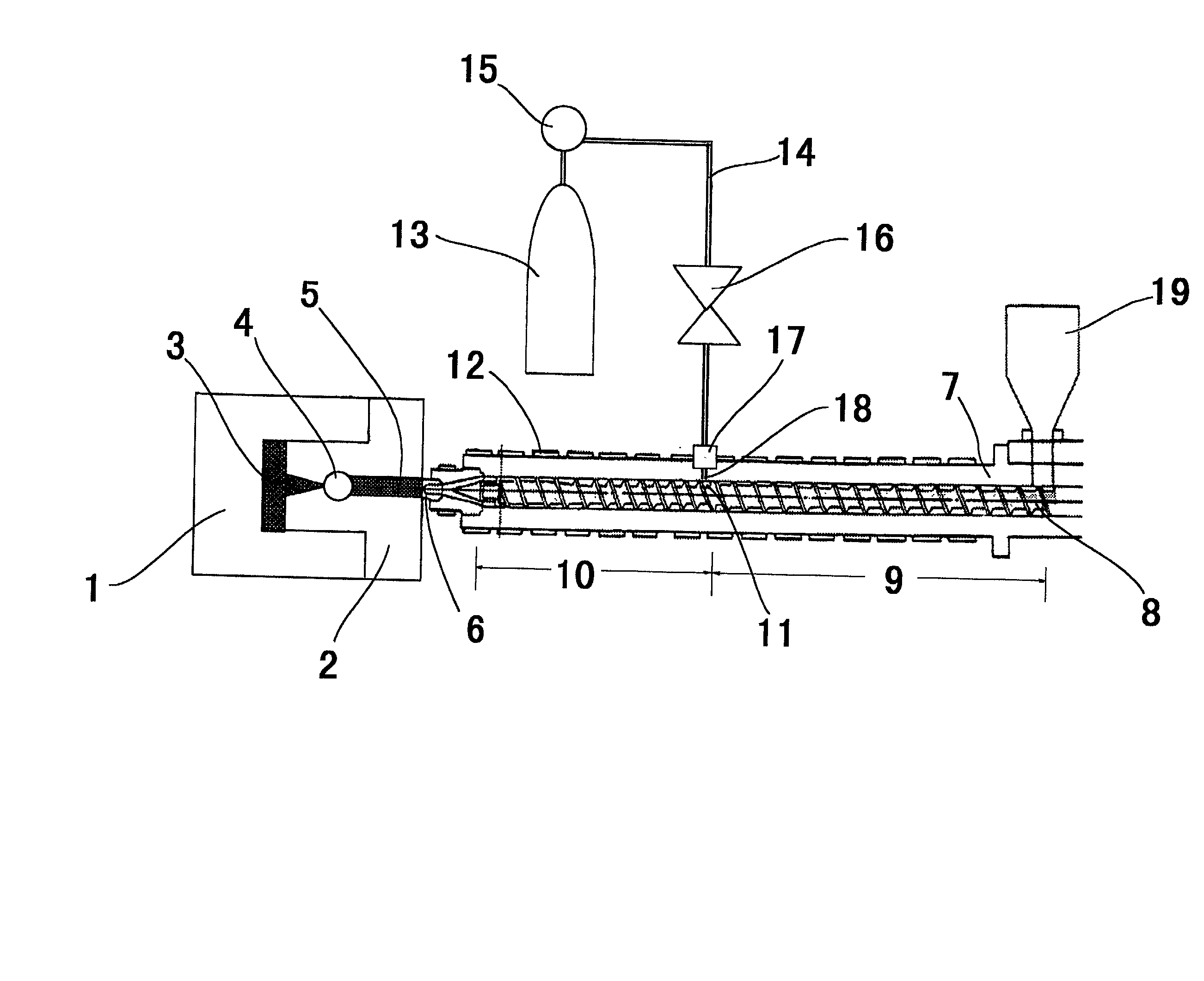
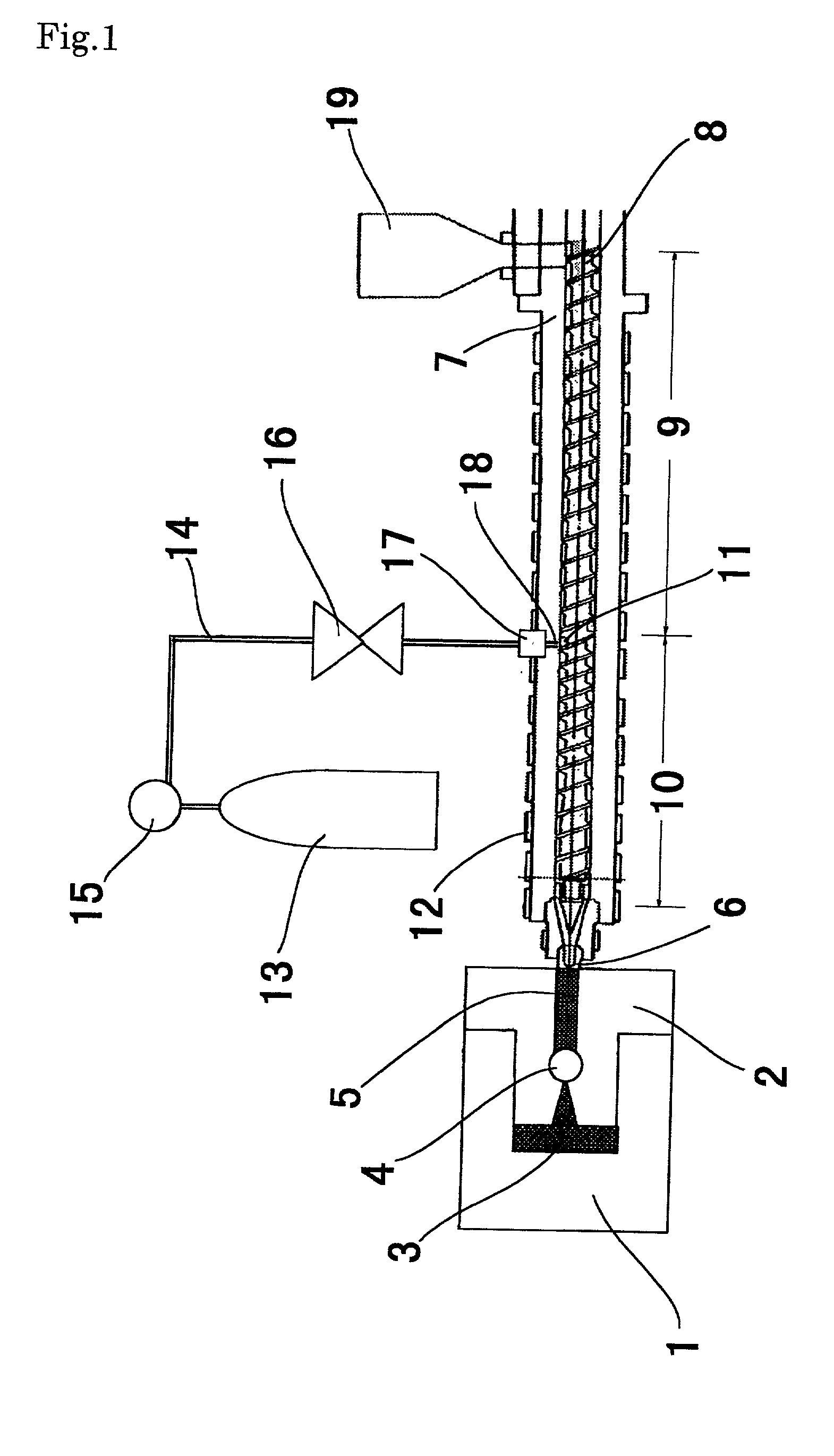
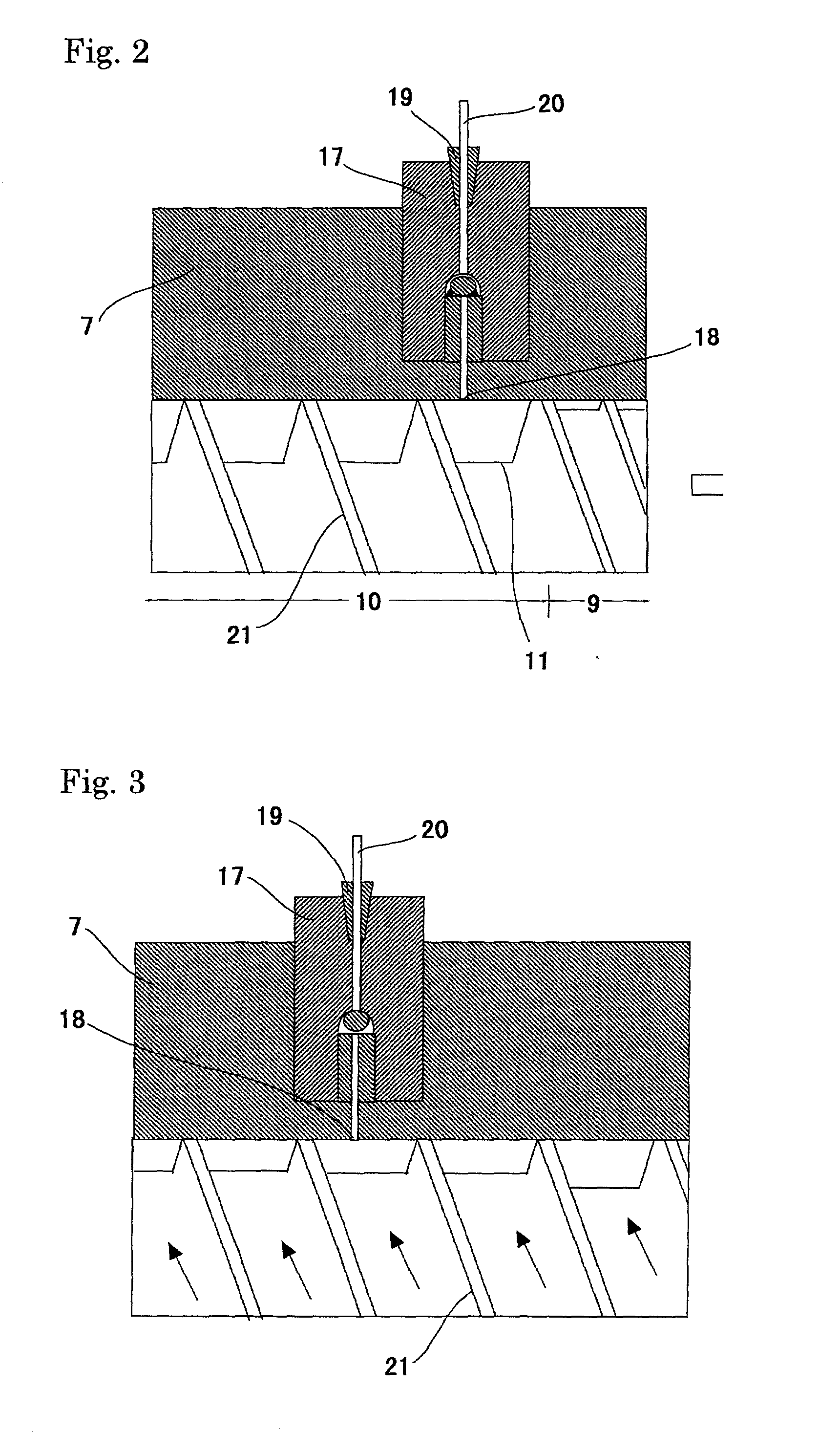
[0127] A screw which had the L / D ratio of 27, the screw outside diameter of 69.8 mm, the first-stage compression section having the L / D ratio of 14D (the flat area having 7.3 mm of groove depth from the hopper bottom was 9D, and the following area in which the groove depth decreased evenly from 7.3 mm to 3.1 mm is 5D), and the second-stage compression section having the L / D ratio of 13D (the flat area having 11 mm of groove depth from the hopper bottom was 7D, and the area in which the groove depth decreased evenly from 11 mm to 5 mm is 6D) was mounted on IS-450GS-27 (mold clamping force: 450 tons; the straight-hydraulic mold clamping system), available from Toshiba Machine Co., Ltd., which was used as the injection molding machine. The distance between the grooves in the screw was constant. A physical foaming agent injection hole having 2 mm of inside diameter was made in the cylinder at a location corresponding to the 2D area of the second-stage compression section at the time of ...

examples 4 to 6

[0139] Injection foaming was carried out in the same manner as described in Examples 1 to 3 except that as the foaming agent, 0.04 wt % citric acid and 0.06 wt % sodium hydrogencarbonate were added.

[0140] The pressure of the physical foaming agent bomb, injection pressure, addition amount, cavity clearance, thickness of the foam product, expansion ratio, average cell diameter, maximum cell diameter, skin layer thickness, smoothness and status of occurrence of flash or silver streak are shown in Table 2.

[0141] Compared with Examples 1 to 3, the cell diameter was uniform, and microcells were formed. Compared with Examples 1 to 3, the average cell diameter was small, and the appearance was better.


PUM

PropertyMeasurementUnit
particle diameteraaaaaaaaaa
average particle diameteraaaaaaaaaa
thicknessaaaaaaaaaa

Abstract

A process for injection-foaming a thermoplastic resin by using an injection molding machine with a two-stage-compression screw, injecting a physical foaming agent into the cylinder of the machine at a pressure lower than the storage pressure of the physical foaming agent, mixing it with a melted resin and expanding the volume of the cavity of the mold at the time of injection, and an injection molding machine and resin composition suitable therefore.

Description

[0001] This invention relates to an injection foaming process in which a physical foaming agent is injected into an injection molding machine and mixed with a melted thermoplastic resin before injection foaming, and to an injection molding machine and resin composition suitable therefore. More specifically, this invention relates to a process for obtaining a foam by injecting a physical foaming agent into the cylinder of an injection molding machine at a pressure lower than the storage pressure of the physical foaming agent, mixing it with a melted resin and expanding the volume of the cavity of the mold at the time of injection, and to an injection molding machine and resin composition suitable therefore.TECHNICAL BACKGROUND[0002] In the past, study has been made of the use of an injection molding method using thermoplastic resin in which foaming is conducted with an aim of reducing materials usage and product weight. As the method for carrying out injection foaming, a method in wh...

Claims


Application Information

Patent Timeline
Patent Type & Authority Applications(United States)
IPC IPC(8): B29C44/34B29C44/58
CPCB29C44/3446B29C44/348B29C44/586B29D35/142B29D35/148
Inventor SUGIHARA, EIICHIERIGUCHI, MICHIOMISUMI, MASAKI
Owner MITSUI CHEM INC
Why Eureka
Try Eureka