Torque transmitting apparatus

a transmission apparatus and transmission tube technology, applied in the direction of rotary clutches, gearings, fluid couplings, etc., can solve the problems of rapid destruction of friction linings, inability to absorb excess heat in the fluid medium of the torque converter housing, and generation of heat in such quantities, so as to achieve the effect of dissipating heat in the torque converter

Inactive Publication Date: 2002-03-07
LUK LAMELLEN & KUPPLUNGSBAU BETEILIGUNGS KG
View PDF1 Cites 31 Cited by
  • Summary
  • Abstract
  • Description
  • Claims
  • Application Information

AI Technical Summary

Benefits of technology

0006] An object of the instant invention is to provide a novel and improved arrangement which renders it possible to withdraw heat from and / or to dissipate heat in a torque converter at a rate which is required to avoid damage to various heated heat-sensitive parts and / or substances, such as friction linings, oil, transmission fluid and the like.

Problems solved by technology

Partial engagement of the bypass clutch involves a slip of the piston relative to the housing and / or vice versa, and such slip results in the generation of heat in such quantities that the fluid medium in the housing of the torque converter is not always capable of absorbing excess heat.
Excessive heating of friction linings forming part of the bypass clutch can entail damage to and frequently rapid destruction of the friction linings; in addition, overheating can adversely influence the hydraulic fluid in the housing of the torque converter.
Abrupt full engagement of the bypass clutch, i.e., without slip, is likely to be even more damaging to the torque converter and can also adversely affect the comfort to the occupant(s) of the motor vehicle.
Thus, an abrupt transition from disengagement to full engagement of the bypass clutch can be a cause of discomfort to the occupant(s).
Such requirements cannot be met, or cannot be adequately satisfied, by presently known torque converters.

Method used


Image

  • Torque transmitting apparatus
  • Torque transmitting apparatus
  • Torque transmitting apparatus

Examples


Embodiment Construction

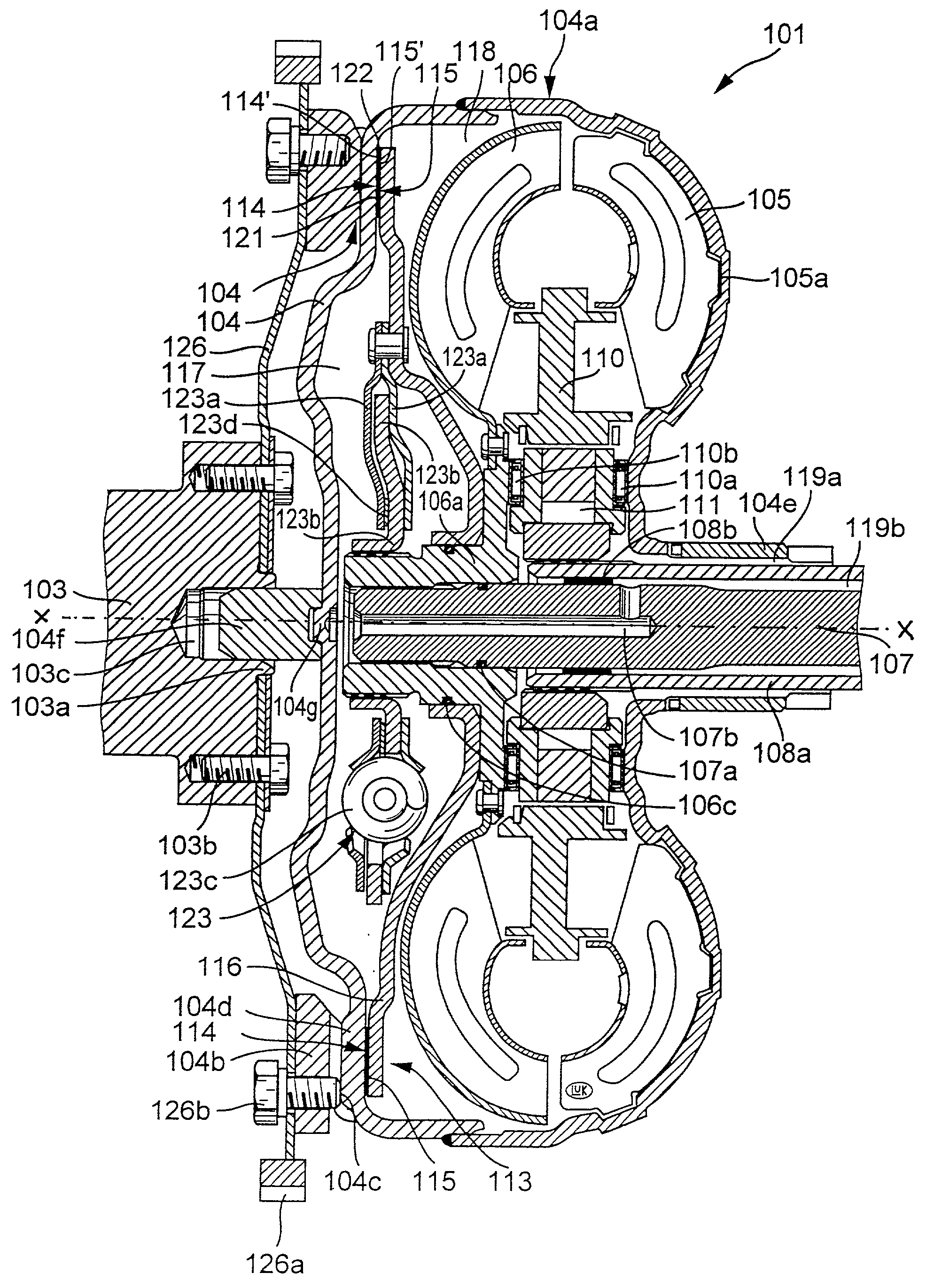
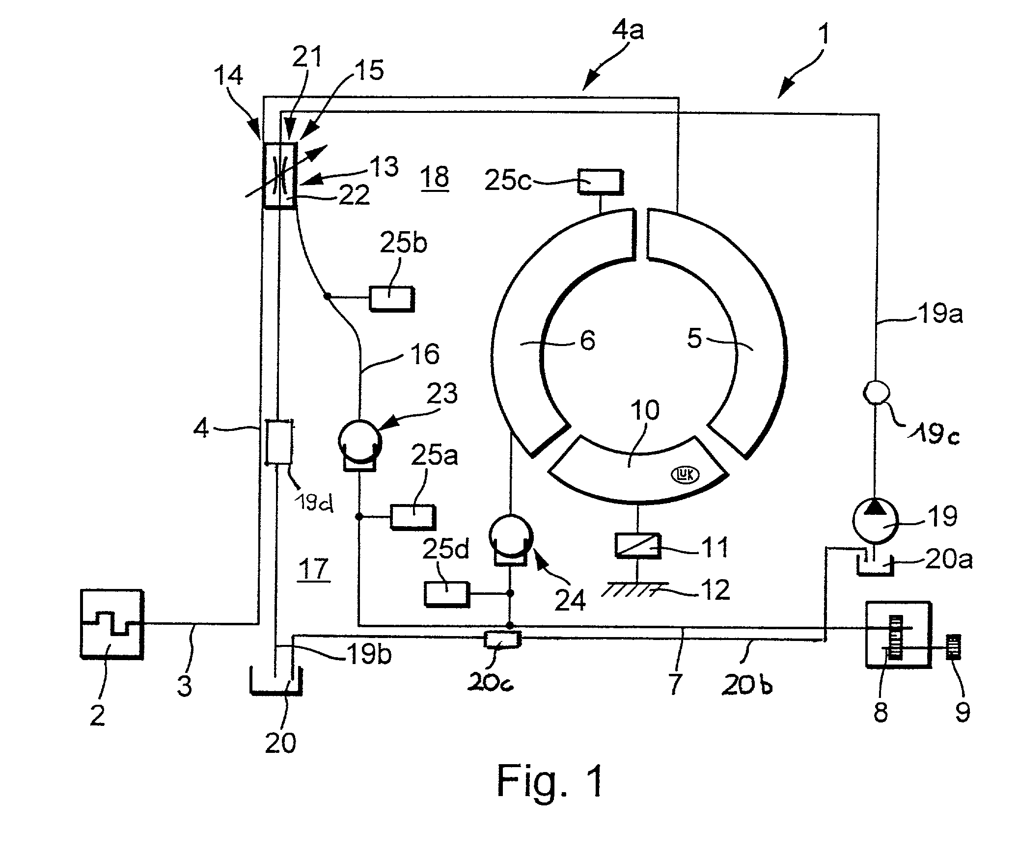
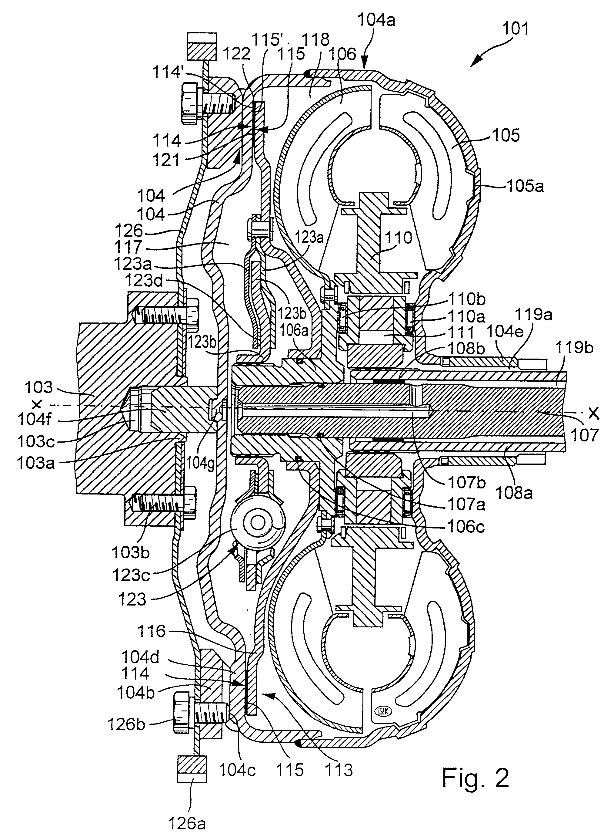
[0109] Referring first to FIG. 1, there is shown a hydrokinetic torque converter 1 having a housing 4a rotatable about a predetermined axis (see the axis X-X shown in FIG. 2) by a prime mover 2. The latter can constitute an internal combustion engine of the type employed in motor vehicles, an electric motor, a gas turbine or a hybrid drive means. The output shaft 3 of the prime mover 2 can be fixedly of force-lockingly connected with a portion 4 of the housing 4a in any one of a number of different ways. The portion 4 which is shown in FIG. 1 is a flexible annular metallic washer-like wall which drives the other part or parts of the housing 4a and also a rotary pump 5 of the torque converter 1. A turbine 6 of the torque converter is coaxial with and is normally rotated or can be rotated by the pump 5 by way of a body of hydraulic fluid in the housing 4a. FIG. 1 further shows a stator 10 which constitutes an optional part of the torque converter 1.

[0110] The output element 7 of the t...


PUM


Abstract

A hydrokinetic torque converter with a built-in bypass clutch is provided with an arrangement which regulates the cooling of the clutch at a rate dependent upon the slip between the coaxial driving and driven parts of the clutch, and hence upon the quantity of generated friction heat. The cooling unit for the driving and/or driven part of the clutch can employ, for example, one or more pumps; a supply of a substance which changes its aggregate state from liquid to gaseous or from solid to flowable in response to heating, and vice versa in response to cooling; one or more porous washers in the path for the flow of hydraulic fluid between the customary plenum chambers provided in the housing of the torque converter to move a piston of the driven part of the clutch into and from frictional engagement with the housing; and/or a system of recesses, grooves, channels and/or other passages serving to convey fluid between the chambers at a rate which is higher or highest when the clutch operates with maximum slip. Such rate can decrease to zero when the torque converter is idle or the clutch is fully engaged to operate without slip.

Description

[0001] The present invention relates to improvements in torque transmitting apparatus, and more particularly to improvements in hydrokinetic torque converters of the type often utilized in the power trains of motor vehicles, e.g., to transit torque between the output element of a prime mover (such as a crankshaft or a camshaft of a combustion engine) and the input shaft of a changespeed transmission.[0002] A torque converter of the character to which the present invention pertains normally comprises a rotary housing which is driven by the prime mover and drives a vaned pump, a vaned turbine which can be rotated by the body of fluid filling the housing and being circulated by the pump when the prime mover is on, an optional stator between the pump and the turbine, and a so-called bypass clutch or lockup clutch (hereinafter called bypass clutch) which can be engaged to transmit torque from the housing directly to the turbine or to a hub which rotates with the turbine and serves to tra...

Claims


Application Information

Patent Timeline
Patent Type & Authority Applications(United States)
IPC IPC(8): F16H45/02F16H61/14
CPCF16H45/02F16H2045/021F16H2045/0278F16H2045/0289F16H2045/0294F16H41/24
Inventor BACK, GUNNARFRIEDMANN, HUBERTGRANDERATH, PAULHELLER, JEAN-FRANCOISMAIENSCHEIN, STEPHANMEISNER, MARCMULLER, BRUNOREIK, WOLFGANG
Owner LUK LAMELLEN & KUPPLUNGSBAU BETEILIGUNGS KG
Why Eureka
Try Eureka