Acoustic device

a technology of acoustic devices and acoustic waves, applied in the direction of electromechanical transducers, transducer casings/cabinets/supports, electromechanical transducers, etc., can solve the problems of unavoidably high directionality, limited loudness, and large volume, and achieve rapid spreading or augmenting the buildup of bending wave action

Inactive Publication Date: 2002-03-07
GOOGLE LLC
View PDF30 Cites 79 Cited by
  • Summary
  • Abstract
  • Description
  • Claims
  • Application Information

AI Technical Summary

Benefits of technology

[0022] Another useful criterion, and aspect of the invention relative to shape(s) and proportioning of said transverse extents of members hereof, and location(s) of transducer means of "active" acoustic devices, concerns desirability of only a small and orderly spread of transit times for bending waves at resonant mode frequencies relative to the transducer means and reflecting edges of the member, including taking account of the speed of sound, i.e. representative bending waves, being frequency dependent, whether or not in preferred sandwich-type laminated structures, see further below. Close orderly arrivals, say just short of coincidence, of such resonant mode bending waves back at the transducer means after relevant complete traversals of said member involving two edge reflections have highly beneficial effects as to rapid spreading or augmenting buildup of bending wave action out over the whole area of the member.

Problems solved by technology

However, mass and bulk tend to be substantial.
Moreover, sound produced is constrained by its origin with one or more cone elements whose axiality imposes unavoidably high directionality, particularly the higher the frequency; and loudness very noticeably follows the inverse square law of radiation relative to distance, as though from a point source.
Some use stretched webs or films of flexible material clamped at their edges in frames, e.g. along with bonded-on current-carrying strips or wires for electromagnetic drive using large and heavy arrays of perforated magnets, or with applied surface conduction for electrostatic drive from fixed perforated polarised electrode plates requiring large high-voltage transformers and subject to loudness being limited by voltage breakdown.
Drive operation of these stretched film loudspeakers is inherently pistonic, and there tend to be unwanted modal "drum" and related resonances at discrete frequencies requiring specific damping provisions for satisfactory performance.
Not surprisingly, absence of any design control over attachment surfaces / panels, together with no better than moderate efficiency, led only to unpredictable results not satisfactory for high quality sound reproduction.
At least one prima facie attractive and likely mathematical technique, namely statistical energy analysis, is actually ineffective.
We know of a few prior proposals for sound reproduction based on bending wave action, though none appreciate or foreshadow the analysis, understanding and practical teaching hereof.
Only limited working acoustic range is indicated, said to be suited to applications such as public address systems; and operation is again limited to being wholly above the coincidence frequency.
Whilst very high mechanical efficiency is indicated for sound energy conversion, the described panel is so stiff that it is difficult to drive, requiring a very large and cumbersome moving-coil driver.
It is also very expensive to make; and rather heavy, particularly with its support frame.
Limitations in operating frequency range of this proposal were confirmed, and at first appeared to preclude achieving practical loudspeakers, even for public address applications where there is acceptance of limited range / quality of sound reproduction but expectation / requirement for quite low-cost units.
It is also noted that, in contrast to other mathematical techniques, specifically statistical energy analysis, use of finite element analysis could, at least as applied by us, have revealed structural problems as the reasons for frequency limitation of WO92 / 03024 and its poor placement of its drive means being an inappropriate choice.
It was confirmed that most such members have poor acoustical performance, especially at frequencies effectively excluded by WO92 / 03024, i.e. at lower frequencies going below the coincidence frequency and down towards the largest or fundamental wavelengths of possible bending wave vibration for the member concerned.

Method used


Image

  • Acoustic device
  • Acoustic device
  • Acoustic device

Examples


Embodiment Construction

[0026] Our basic research and development has particular relevance to practical implementation of this invention, and is now reviewed in more detail.

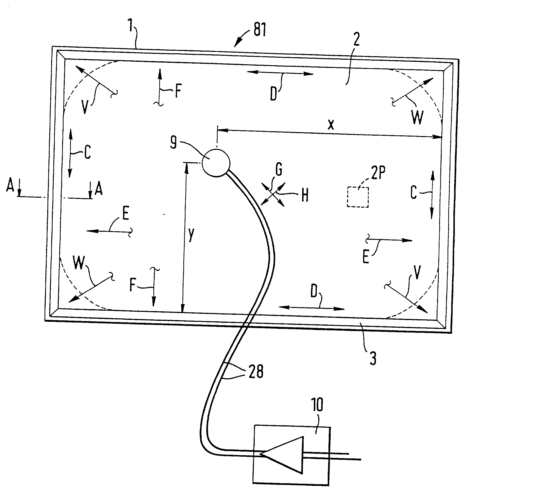
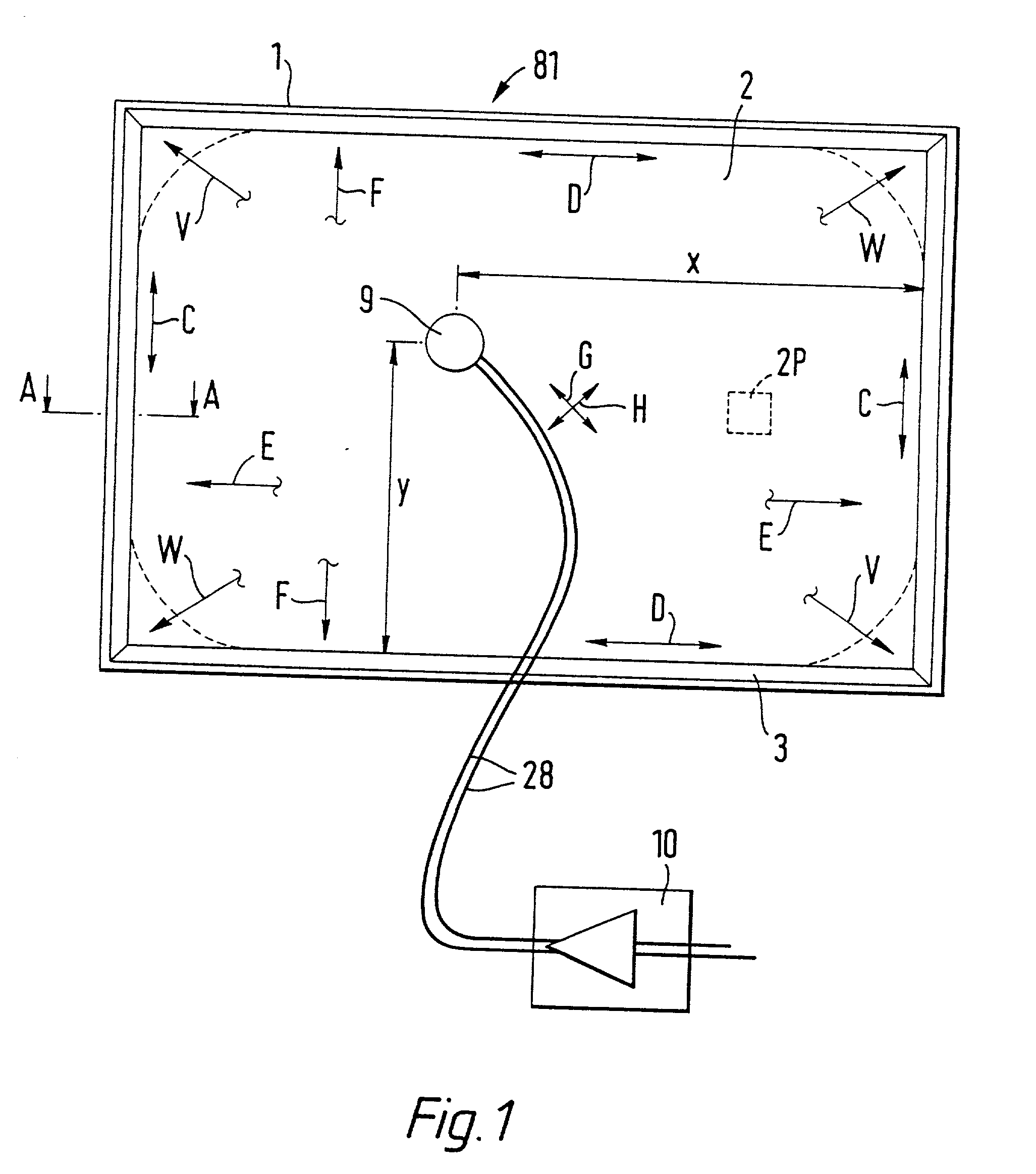
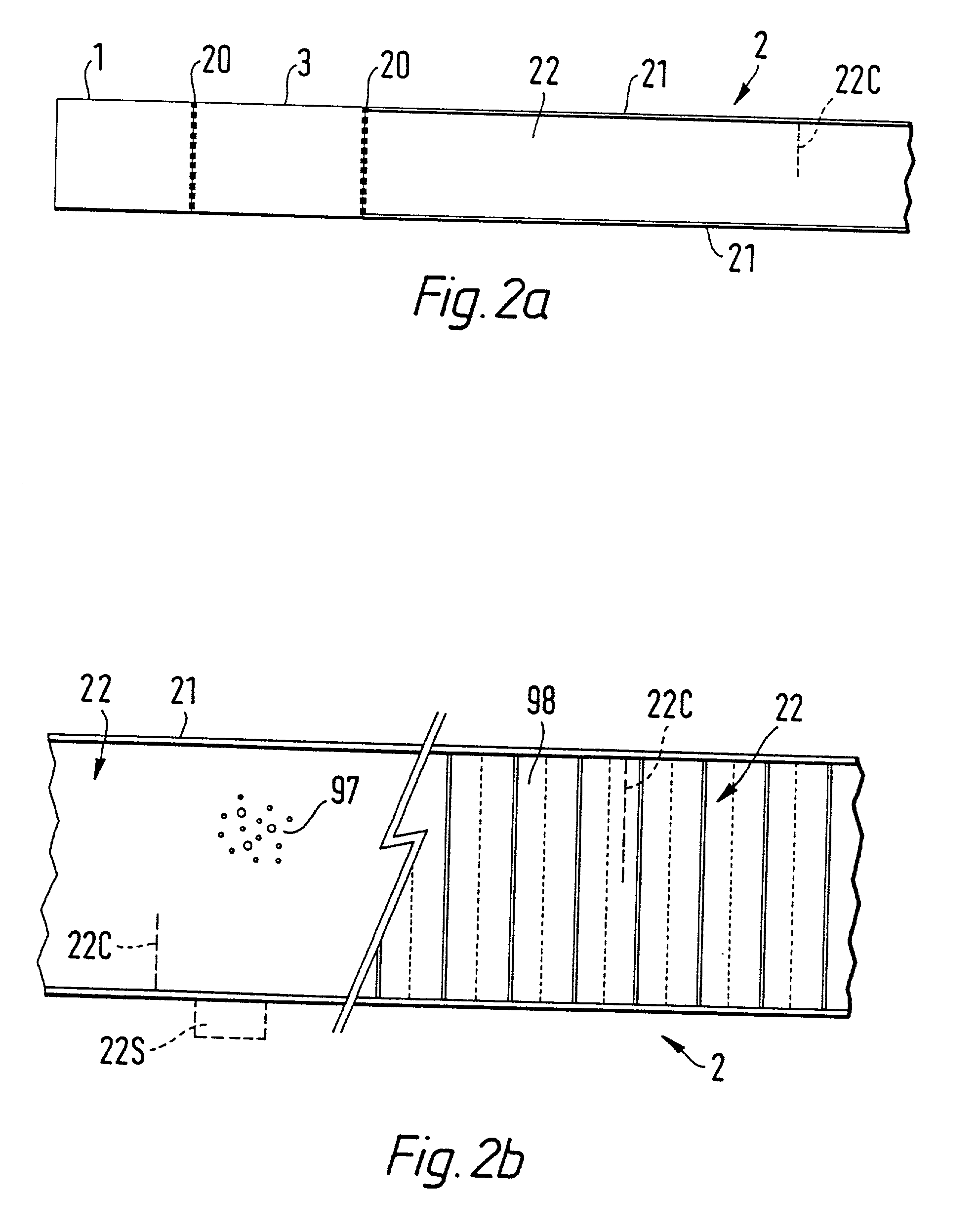
[0027] Many factors actually or potentially contribute to bending wave action, thus frequencies and distribution etc of vibration anti-nodes associated with natural resonant modes in members hereof. As first done for members where relevant materials parameters contributing to actual bending wave action, specifically to bending stiffness, shear etc, were kept substantially the same in all or at least particular directions of interest, it was established that shape and dimensions of the members make particularly significant contributions of great value to realising inventive aspects and achieving practical device embodiments.

[0028] Dimensions, as such, for any particular shape, are mainly effective by their inherent contributions to determining lowest natural frequencies of possible actual bending wave vibration for the member, even to co...


PUM

PropertyMeasurementUnit
bending wave frequencyaaaaaaaaaa
frequencyaaaaaaaaaa
aspect ratioaaaaaaaaaa

Abstract

Acoustic device including a member extending transversely of its thickness and capable of sustaining bending waves at least over an intendedly consequentially acoustically active area of the transverse extent of said member, the member having, by reason of orderly design methodology disclosed and claimed, a distribution of resonant modes of its natural bending wave vibration at least over said area that is dependent on values of particular parameters of said members, including geometrical configuration and directional bending stiffness(es), which values have been selected to predetermine said distribution of natural resonant modes being consonant with required achievable acoustic action of said member for operation of said device over a desired operative acoustic frequency range.

Description

[0001] This application is a continuation of U.S. application Serial No. 08 / 707,012, filed Sep. 3, 1996.[0002] The invention relates to acoustic devices for use in or as loudspeakers when driven or excited, usually by electrical signals via electrodynamic means; or in or as microphones when driven by incident acoustic energy, usually to produce a corresponding electrical signal; or in or for other acoustic devices or purposes.[0003] United Kingdom Patent applications as follows: No. 95 / 17918 filed Sep. 2, 1995 for "Acoustic Device" No. 95 / 22281 filed Oct. 31, 1995 for "Acoustic Device" No. 96 / 06836 filed Mar. 30, 1996 for "Acoustic Device" from which priority is claimed are hereby incorporated by reference, in their entirety, into this application.GENERAL BACKGROUND[0004] Conventional loudspeakers in widespread use employ acoustic air-driving elements of so-called "cone" type. The or each cone element is mechanically driven at its smaller end in a pistonic manner, normally by a movi...

Claims


Application Information

Patent Timeline
Patent Type & Authority Applications(United States)
IPC IPC(8): B42D15/02B60R11/02G06F1/16G06F9/02G07F9/02H04N5/64H04R1/00H04R1/02H04R1/20H04R1/24H04R1/26H04R1/28H04R3/04H04R3/14H04R5/02H04R5/027H04R7/04H04R7/06H04R7/08H04R7/10H04R7/12H04R7/20H04R7/22H04R9/00H04R9/02H04R9/04H04R9/06H04R17/00H04R25/00H04R31/00
CPCB42D15/022Y10T29/49005G06F1/1601G06F1/1605G06F1/1616G06F1/1624G06F1/1688G06F9/02G07F9/02H04R1/021H04R1/025H04R1/028H04R1/24H04R1/26H04R1/2811H04R1/2834H04R3/04H04R5/02H04R5/027H04R7/045H04R7/06H04R7/08H04R9/025H04R9/045H04R9/066H04R17/00H04R2201/021H04R2307/029H04R2440/07H04R2499/13H04R2499/15G10H1/32H04N5/642H04R3/14H04R7/10H04R7/12H04R7/20H04R31/003H04R2205/024H04R2307/201H04R2400/07H04R2440/03H04R2440/05H04R2499/11B60R11/0217
Inventor AZIMA, HENRYCOLLOMS, MARTINHARRIS, NEIL
Owner GOOGLE LLC
Why Eureka
Try Eureka