Condenser, power plant equipment and power plant operation method

Inactive Publication Date: 2002-03-14
MITSUBISHI HITACHIPOWER SYST LTD
View PDF0 Cites 21 Cited by
  • Summary
  • Abstract
  • Description
  • Claims
  • Application Information

AI Technical Summary

Problems solved by technology

However, since sea water is used as cooling water in the condenser as mentioned above, sea water has become a cause of corrosion or the like of structural apparatus and piping, etc. of the power plant when the sea water flowed into the condenser, so that it is necessary to monitor always water quality inside the system to find whether or not sea water leaks into the interior of the condenser.
However, in the case where the detection point is provided in the condenser outlet or on the downstream side of the condenser pump for delivering condensate in the condenser, or in the piping connecting the condenser to the steam generator, a time is taken until sea water leakage is detected, whereby there is the possibility that the water mixed with sea water is flowed out from the condenser even if the plant is stopped or a feed water system is closed after the detection of sea water leakage, and that the sea water-mixed water flows into the steam generator and steam turbine since the sea water-mixed water is delivered by the condenser pump.

Method used


Image

  • Condenser, power plant equipment and power plant operation method
  • Condenser, power plant equipment and power plant operation method
  • Condenser, power plant equipment and power plant operation method

Examples


Embodiment Construction

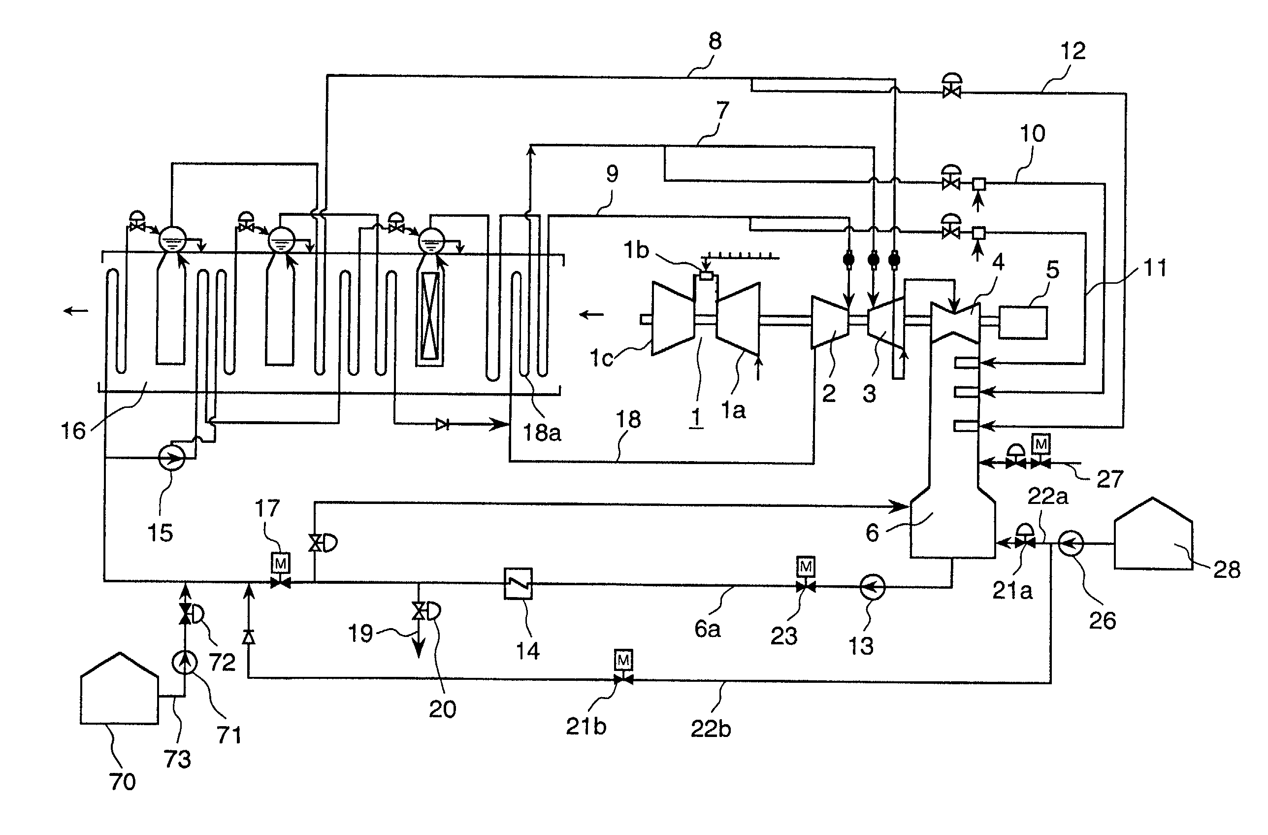
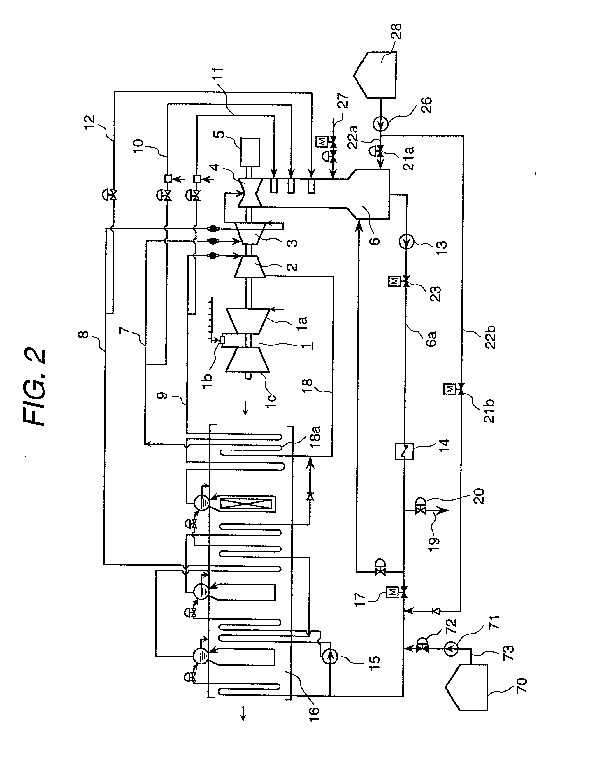
[0058] FIG. 2 is a diagram of a system construction of a power plant of an embodiment of the present invention.

[0059] A power plant of the present embodiment is roughly classified as and composed of a gas turbine system, a steam turbine system, a condenser, a feed water system and a steam generator system.

[0060] The gas turbine system is composed of a compressor la compressing air, a combustor 1b mixing the air compressed by the compressor 1a with fuel and burning them, a gas turbine 1c driven by the combustion gas burnt by the combustor 1b.

[0061] Further, the steam turbine system is composed of a high pressure steam turbine 2, an intermediate pressure steam turbine 3 and a low pressure steam turbine 4. Steam heated by the steam generator system as described later is supplied to the steam turbine system. Further, in the present embodiment, the gas turbine 1, the high pressure steam turbine 2, the intermediate pressure steam turbine 3 and the low pressure steam turbine 4 have a drivi...


PUM


Abstract

Water quality detecting points for detecting sea water leakage are provided at a portion in a hot well zone right under a tube bundle of heat exchange tube forming a steam condensing zone and at a condenser outlet allowing the condensate to be led out of the condenser or in the vicinity thereof, and a difference between detection values at both detecting points is monitored. Further, when leakage of sea water occurred, a feed water stop valve or a condensate stop valve is stopped for separating the system in which the sea water is mixed, and at same time, make-up water is supplied to a steam generator. Further, chemical or chemical dilution water is injected into the condensate mixed with sea water.

Description

[0001] 1. Technical Field of the Invention[0002] The present invention relates to a condenser, a power plant and an operation method thereof.[0003] 2. Description of Prior Arts[0004] In a fossil power plant, nuclear power plant, or the like, steam exhausted from a steam turbine is cooled by a condenser using sea water as cooling water. However, since sea water is used as cooling water in the condenser as mentioned above, sea water has become a cause of corrosion or the like of structural apparatus and piping, etc. of the power plant when the sea water flowed into the condenser, so that it is necessary to monitor always water quality inside the system to find whether or not sea water leaks into the interior of the condenser. If the water quality inside the system exceeds a set value because of leakage of sea water into the interior of the condenser, a signal is issued from a detection part, and an alarm is generated on a monitor, operation panel, etc. An operator has received the ala...

Claims


Application Information

Patent Timeline
Patent Type & Authority Applications(United States)
IPC IPC(8): F28B11/00F28F19/00
CPCF28B11/00F28F19/00F28F2265/16
Inventor KANGAI, NAOKIOHTOMO, KAZUHIROSUDO, MITSURU
Owner MITSUBISHI HITACHIPOWER SYST LTD
Why Eureka
Try Eureka