Permanent magnet brushless electric motor system and method of using same

a permanent magnet, electric motor technology, applied in the direction of motor/generator/converter stopper, electric motor speed/torque regulation, dynamo-electric converter control, etc., can solve the problem of reducing the torque-per-amp performance of the motor, adding to the torque pulsation of the typical bldc motor, and further limited conventional prior art bldc motors

Inactive Publication Date: 2002-04-18
VSCF
View PDF0 Cites 38 Cited by
  • Summary
  • Abstract
  • Description
  • Claims
  • Application Information

AI Technical Summary

Problems solved by technology

Further, any error in the timing of the off-on-off action of the electronic power switches relative to the rotor position adds to the torque pulsations of the typical BLDC motor.
Further, any errors in the placement or position of the sensors relative to the armature windings decreases the torque-per-amp performance of the motor.
Conventional prior art BLDC motors are further limited to an inherent maximum motoring rotational speed determined by the magnitude of the DC voltage applied to the control system.
Special, and c

Method used


Image

  • Permanent magnet brushless electric motor system and method of using same
  • Permanent magnet brushless electric motor system and method of using same
  • Permanent magnet brushless electric motor system and method of using same

Examples


Embodiment Construction

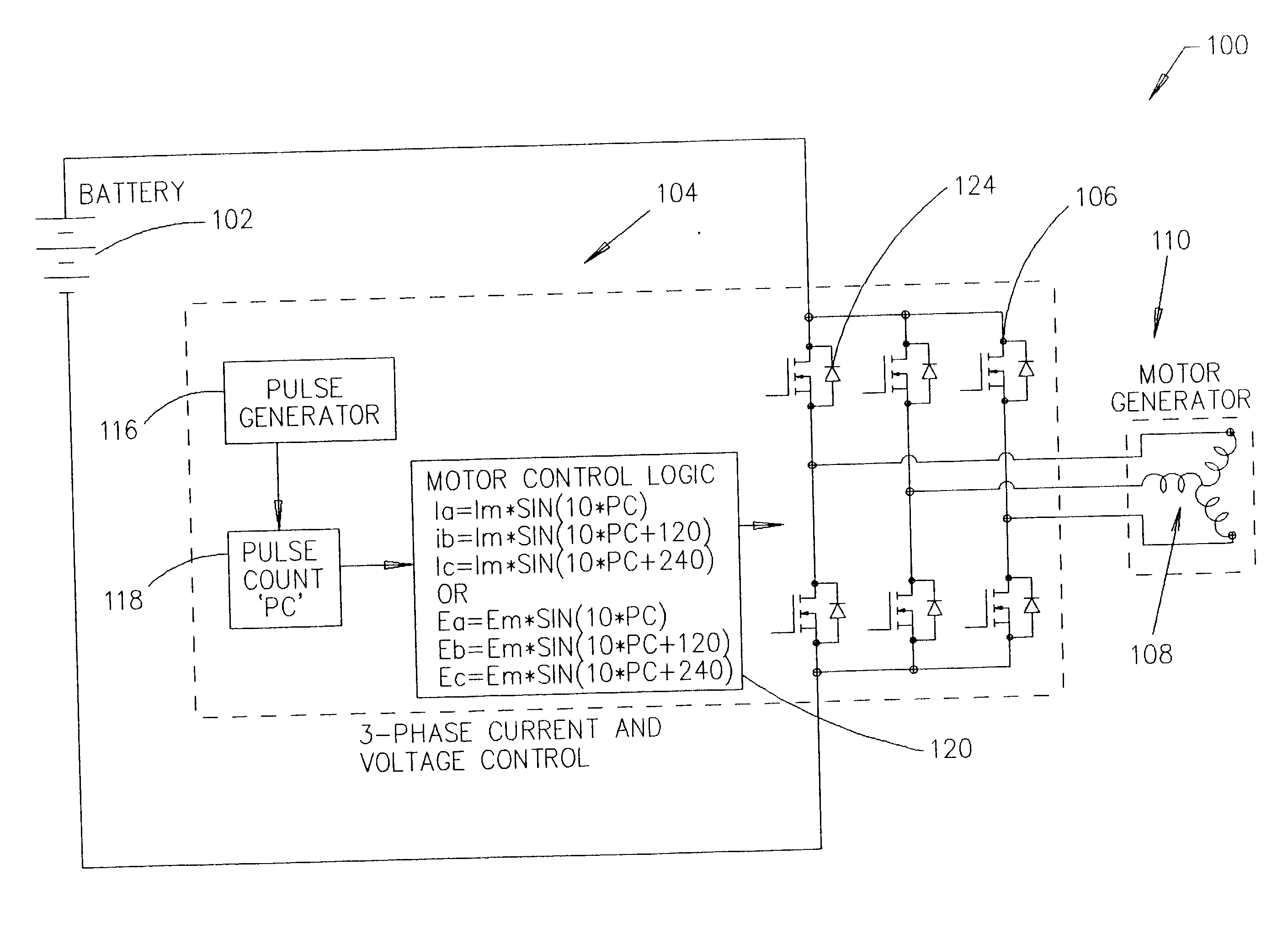
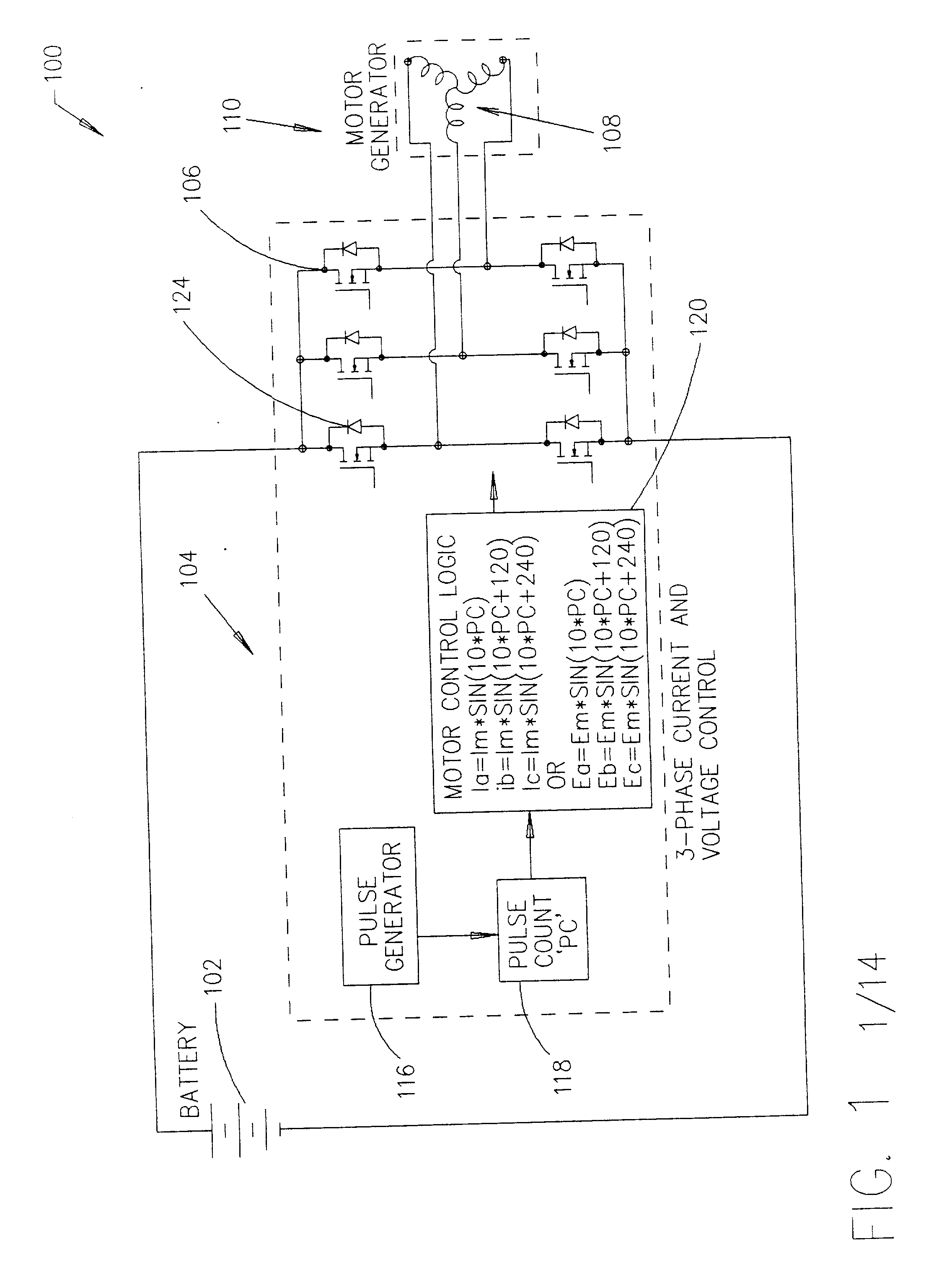
[0031] A device according to one embodiment of the invention may use a form of flux vector control of a permanent magnet synchronous AC motor to develop full rated torque from zero rotational speed up to full rated speed. A motor-generator according to the invention may be used, for example, as a starter for aircraft engines and as a power generator for the aircraft.

[0032] The flux vector mode of operation or control of the motor of this invention enables the motor system to substantially lock the rotor magnetic field and the stator armature magnetic field together at zero rotational speed, and to develop full rated torque from zero speed up to full rated operating rotational speed.

[0033] This invention also provides means to selectively change from the flux vector control mode of operation to a `volts per HZ` mode of operation at some selected speed to enable the motor to operate at substantially a 1.0 power factor with minimum `amps per unit torque`.

[0034] In the `volts per HZ` mo...


PUM


Abstract

A brushless motor-generator has a stator with armature windings for polyphase operation and a rotor having at least one pair of permanent magnet poles. A controller varies the magnitude of the alternating-current voltage applied to the armature windings for controlling the operating motor power factor to permit the rotor magnetic field to operate at the optimum or at least at an improved torque angle with respect to the stator magnetic field in the motoring mode, with little or no torque pulsations at substantially all or at least most conditions of motor load.

Description

[0001] 1. Field of the Invention[0002] The present invention relates to permanent magnet brushless electric motors. More specifically, this invention relates to means for operating a permanent magnet brushless electric motor as an AC synchronous motor with full rated starting torque capability and minimum `amps per unit torque` under substantially all loading conditions.[0003] 2. Related Art[0004] Variable speed permanent magnet (PM) brushless DC (BLDC) motors are commonplace today. The basic prior art BLDC motors incorporate a stator having a 3-phase armature winding and a permanent magnet rotor mounted coaxially within the stator structure. The motor also incorporates some form of rotor shaft or rotor magnetic field position sensor, such as Hall Effect sensors, back EMF sensors, synchronous resolvers, etc.[0005] The sensors act to control the off-on-off timing of electronic power switches controlling the flow of electric current in the 3-phase AC windings of the stator armature to...

Claims


Application Information

Patent Timeline
IPC IPC(8): H02P6/08H02P6/20
CPCH02P6/20H02P6/085
Inventor HALLIDY, WILLIAM M.
Owner VSCF
Why Eureka
Try Eureka