Microfluidic devices and methods for producing pulsed microfluidic jets in a liquid environment

a microfluidic device and liquid environment technology, applied in the field of microsurgical procedures, can solve the problems of collateral damage to surrounding tissue, damage far beyond the application site, and damage to the walls of the vessel, so as to reduce collateral damage and retain effective tissue cutting

Inactive Publication Date: 2002-04-18
THE BOARD OF TRUSTEES OF THE LELAND STANFORD JUNIOR UNIV
View PDF2 Cites 47 Cited by
  • Summary
  • Abstract
  • Description
  • Claims
  • Application Information

AI Technical Summary

Benefits of technology

0038] With respect to tissue cutting, the subject methods and devices find use in clot disintegration for stroke treatment and angioplasty (removal of occlusions in blood vessels). When used to cut tissue, the distance between the aperture and the tissue may vary, where the distance typically ranges from about 0 to 10 mm, usually from about 0 to 1 mm, and may be chosen to reduce collateral damage while retaining effective tissue cutting. The subject devices may also be used for treatment of vein occlusions to "massage" veins by the water flow pushing the clots downstream without introduction of the device inside the blood vessel.
0039] The subject methods and devices also find use in the introduction of fluid into small objects, e.g. cells and the like. In such applications, the fluid which is introduced into the microfluid chamber is the fluid that is desired to be introduced into the object. The object is placed over the aperture and the device is actuated to produce the microjet of fluid that enters the object, thereby introducing fluid into the object. In these embodiments, the distance between the object and the aperture generally ranges from about 0 to 100 .mu.m, usually from about 0 to 10 .mu.m . Applications where this particular type of protocol finds use include delivery of macromolecules into cells such as proteins, DNA and the like.

Problems solved by technology

However, both optical and electric discharge techniques suffer from collateral damage to surrounding tissue.
For example, while the vaporization and thermal tissue change due to high plasma temperature are confined to a small area at the probe tip dependent on energy and pulse duration, acoustic transients, bubble expansion and collapse can cause damage far beyond the application site.
For example, three-dimensional expansion of the bubble formed inside blood vessels during the laser angioplasty may introduce damage to the walls of the vessel and cause restenosis similarly to the damage introduced during the baloon angioplasty.

Method used


Image

  • Microfluidic devices and methods for producing pulsed microfluidic jets in a liquid environment
  • Microfluidic devices and methods for producing pulsed microfluidic jets in a liquid environment
  • Microfluidic devices and methods for producing pulsed microfluidic jets in a liquid environment

Examples


Embodiment Construction

.

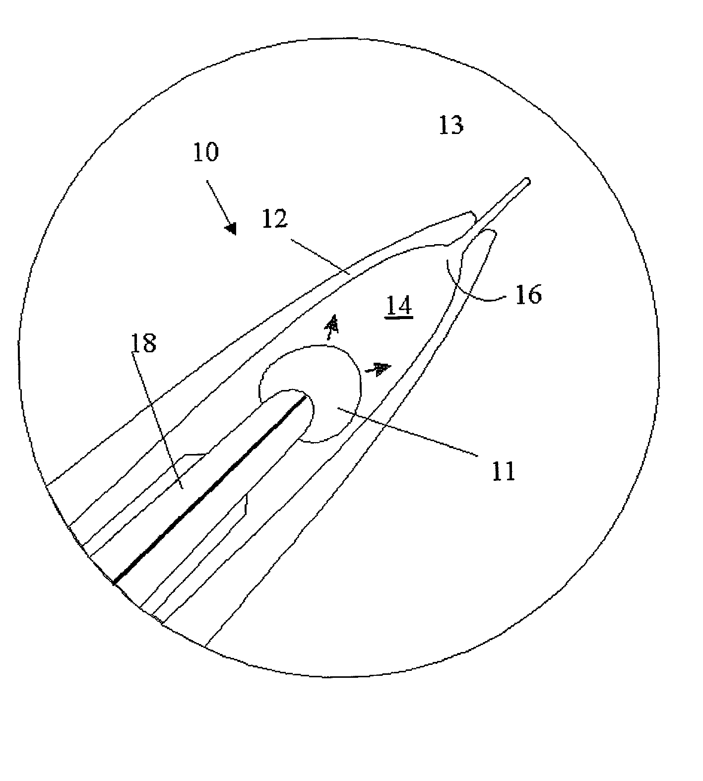
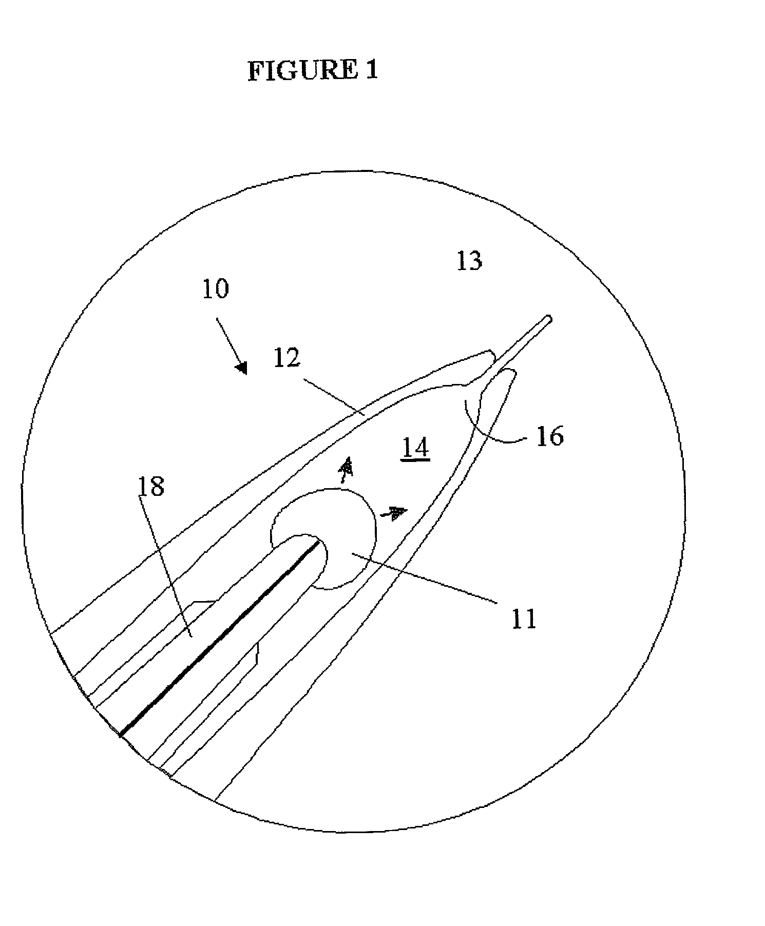
Pulsed Liquid Microjet

[0042] A.Fabrication

[0043] The micronozzle is fabricated from borosilicate glass or quartz. A capillary tube is heated by a CO.sub.2 laser and pulled in a pipette-pulling instrument to give the desired taper and wall thickness. The tapered tube is polished to open the exit hole of the aperture. Under a microscope, the tip of the polished nozzle is heated to thicken the exit hole walls and reflow the glass to the desired exit hole size. The nozzle is mounted and secured over a high-voltage electrode the size of a hypodermic needle that provides the rapid pressure pulse. Prior to use, the nozzle must be filled with a solution, such as saline, which is ejected during a pressure pulse.

[0044] B.Testing

[0045] A small-diameter hole is produced in a gel to simulate tissue cutting. A pulsed liquid microjet as described above, with the nozzle mounted on a high-voltage electrode, is filled with saline solution. A gel is immersed in saline and the tip of the microjet is b...


PUM


Abstract

Microfluidic devices and methods for their use in producing pulsed microfluidic jets in a fluid environment are provided. The subject microfluidic devices are characterized by the presence of a microfluid chamber at their distal ends. The microfluid chamber is bounded by an opening at one end, a vapor producing means opposite the opening, and side walls between the opening and the vapor producing means. The microfluid chambers are further characterized in that the only way fluid can exit the microfluid chambers is through the opening. In using the subject devices to produce a fluid jet in a fluid environment, the chamber is first contacted with the fluid environment. The vapor producing means is then actuated in a manner sufficient to produce a vapor bubble in the chamber which, in turn, produces a microfluidic jet in the fluid environment. The subject devices and methods find use in a variety of different applications, e.g., cutting tissue, introducing fluid into a cell, and the like.

Description

[0001] This application is a continuation-in-part application of application Ser. No. PCT / US00 / 13762 filed May 19, 2000 and designating the United States; which application claims priority pursuant to 35 U.S.C. .sctn.119 (e) to the filing date of the U.S. Provisional Patent Application Serial No. 60 / 135,827 filed May 21, 1999; the disclosures of which applications are herein incorporated by reference.BACKGROUND OF INVENTION[0002] 1. Field of the Invention[0003] The field of the invention is microsurgery, and particularly surgical tools for use therein, and more particularly microsurgical cutting tools.[0004] 2. Background of the Invention[0005] Microsurgery is a broad term that refers to any surgical procedures performed under the magnification of a surgical microscope. Microsurgery is being employed to treat an increasing number of conditions, as it provides a number of benefits over conventional surgical techniques. Such advantages include avoidance of complications experienced du...

Claims


Application Information

Patent Timeline
Patent Type & Authority Applications(United States)
IPC IPC(8): A61B17/22A61B17/32A61F9/007A61F9/011
CPCA61B17/3203A61B2017/22008A61F9/00825A61B2018/263A61F9/00736A61B2017/32032
Inventor FLETCHER, DANIEL A.PALANKER, DANIEL
Owner THE BOARD OF TRUSTEES OF THE LELAND STANFORD JUNIOR UNIV
Why Eureka
Try Eureka