Rotary electric machine having a flux-concentrating rotor and a stator with windings on teeth

a technology of stator and rotor, which is applied in the direction of rotating parts of magnetic circuits, and shape/form/construction of magnetic circuits, etc., can solve the problems of rotors being detached, machine is not designed to rotate at high speed of rotation, and the manufacturing cost is low, so as to achieve the effect of high power

Inactive Publication Date: 2002-04-25
MOTEURS LEROY SOMER
View PDF81 Cites 122 Cited by
  • Summary
  • Abstract
  • Description
  • Claims
  • Application Information

AI Technical Summary

Benefits of technology

[0007] There exists a need for rotary electric machines that are reliable, of relatively high power, of low cost to manufacture, and that remedy the above-mentioned drawbacks in full or in part.

Problems solved by technology

As a result, manufacture of the rotor is relatively complex.
In addition, for a rotor that rotates at high speed, the magnets exert shear forces on the pole pieces that can lead to their becoming detached, if they are retained by poor quality fastening.
Such a machine is not designed to rotate at high speeds of rotation since the currents induced at the surface of the rotor at high speeds tend to heat the magnets, and magnets do not withstand high temperatures.
By way of example, when such magnets are mounted on the surface without being fractioned, the limiting speed of rotation is about 200 revolutions per minute (rpm) for a 16-pole rotor, for example, and about 400 rpm for an 8-pole motor, and that is found to be insufficient in certain applications.
One solution for avoiding overheating of the magnets consists in fractioning them, but that complicates manufacture and increases cost.
In addition, the number of magnets to be provided when fractioning is used increases with the square of speed, such that in addition to its cost, that solution becomes physically inappropriate once the required speed is relatively high, e.g. greater than a few thousand rpm.
This causes the stator to be subjected to mechanical stress tending to ovalize it, thus generating vibration and noise.
Finally, the width of the teeth is constant which gives rise to at least two drawbacks: firstly the magnetic material of the stator can become saturated at the roots of the teeth; and secondly replacing a coil requires the stator to be re-impregnated, so as to lock the coil properly in place on the stator, which means that the machine cannot be repaired on site and must be returned to the manufacturer.
The drawback is that torque ripple is generated.
Furthermore, the magnetic flux passes through as many air-gaps as there are sectors, thereby reducing the efficiency of the machine.
Such a rotor is relatively difficult to manufacture because of the presence, in certain embodiments, of narrow lamination portions outside the rotor for holding the pole pieces.
Such a rotor is unsuitable for high speeds of rotation since centrifugal force tends to move apart those regions of each pole piece which clamp onto the corresponding spline formed on the shaft.
Nevertheless, such a solution is not entirely satisfactory since in addition to complicating manufacture of the rotor, the bars tend to become bowed when the rotor is long and / or its speed is high.

Method used


Image

  • Rotary electric machine having a flux-concentrating rotor and a stator with windings on teeth
  • Rotary electric machine having a flux-concentrating rotor and a stator with windings on teeth
  • Rotary electric machine having a flux-concentrating rotor and a stator with windings on teeth

Examples


Embodiment Construction

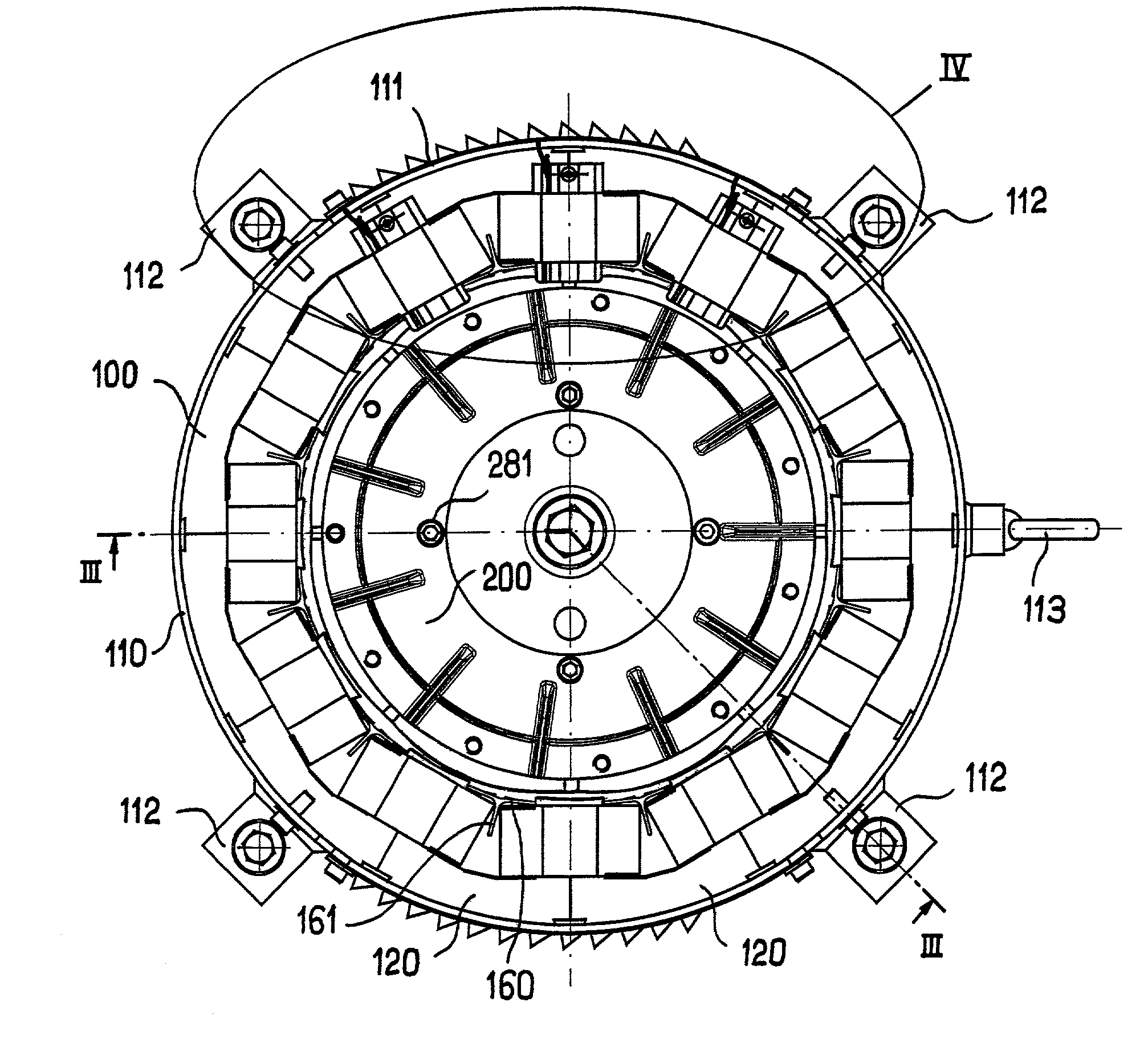
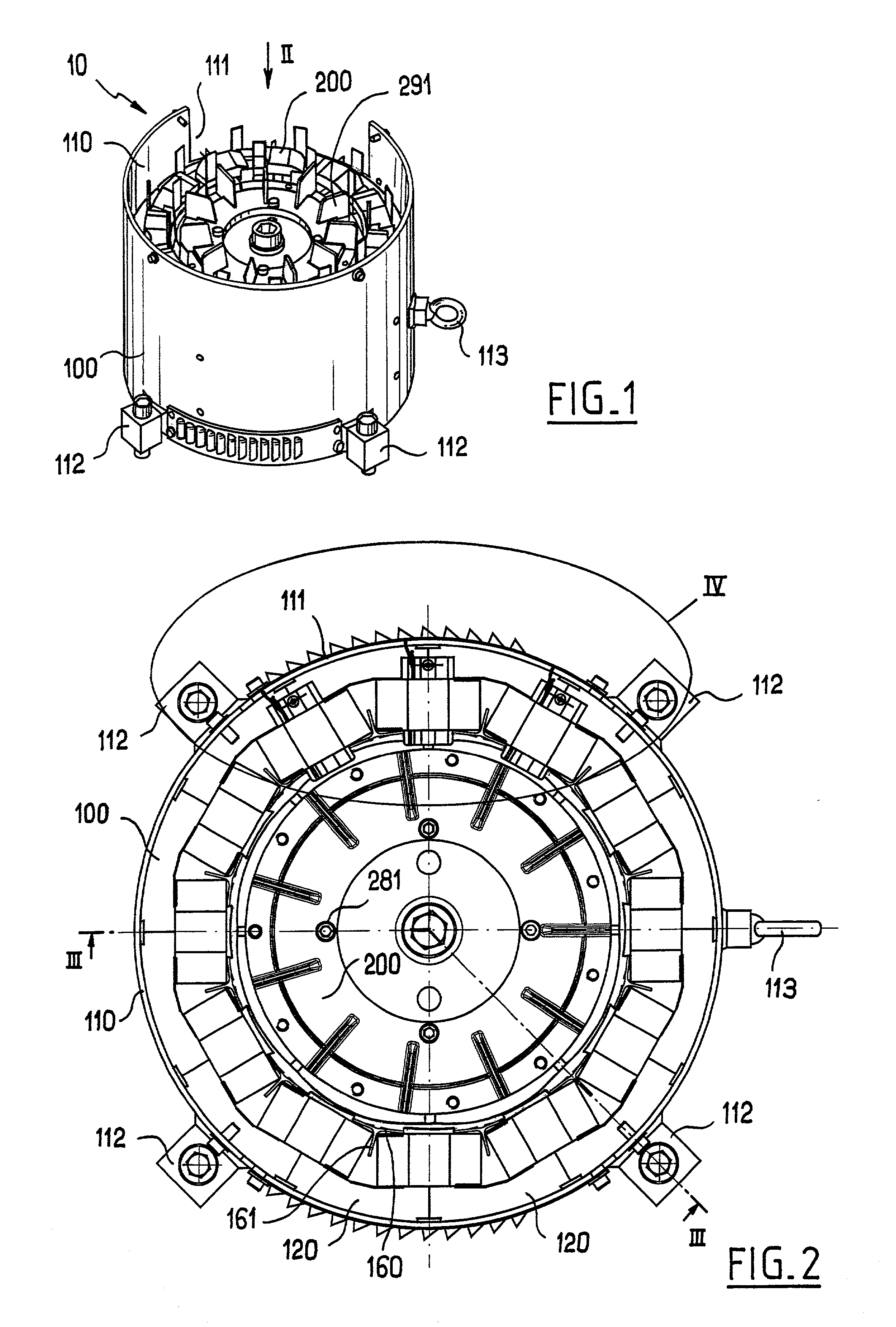
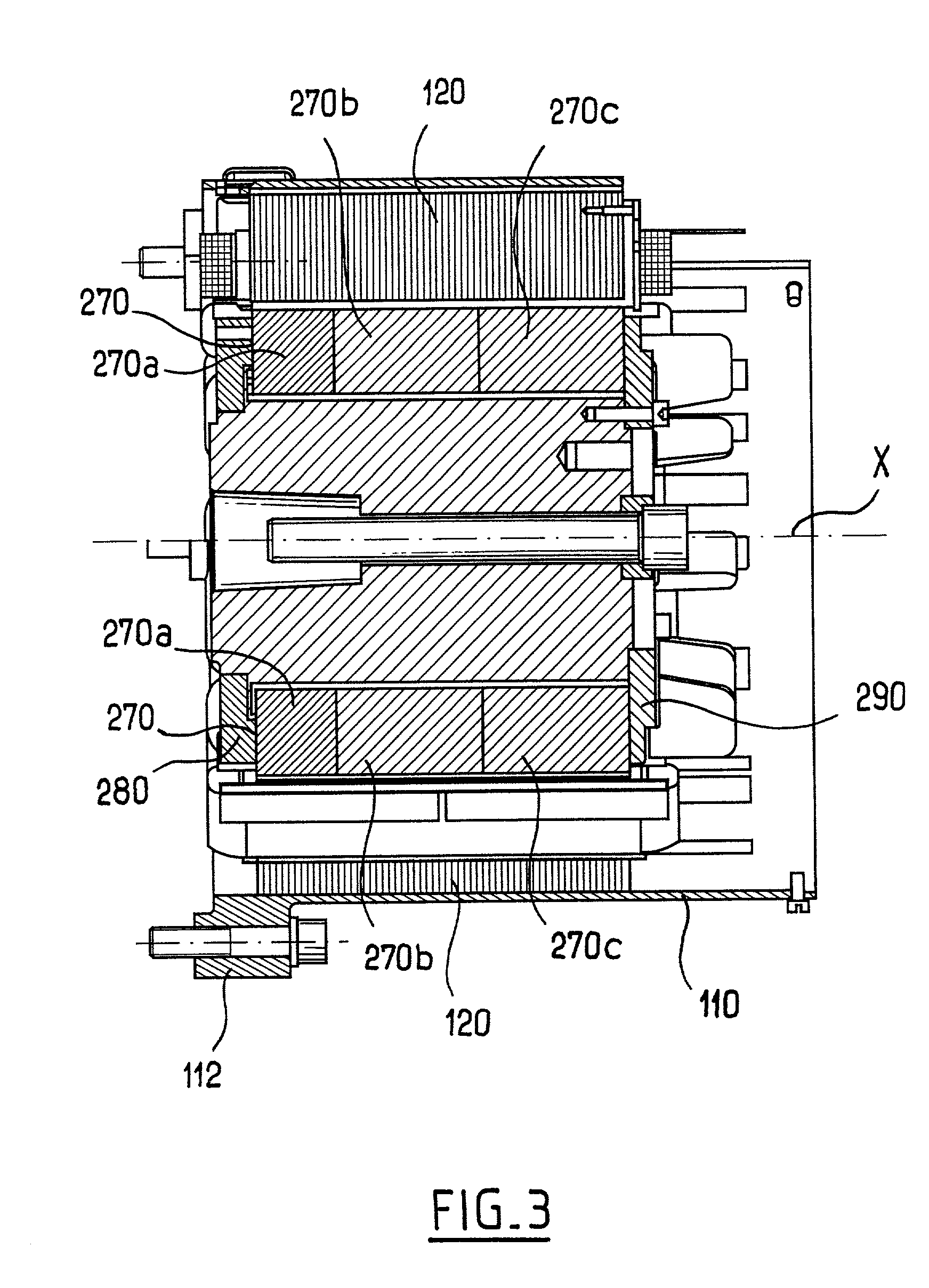
[0057] FIGS. 1 to 4 show a synchronous motor 10 of the invention comprising a stator 100 and a rotor 200. The motor 10 is brushless, it has a flux-concentrating rotor, and its stator has windings on teeth, and it operates on three-phase AC.

[0058] The stator 100 has a steel case 110 with a lateral opening 111 in particular for passing electrical conductors for powering the stator windings. On the outside, the case is provided with fixing tabs 112 and with a hook 113 for hoisting purposes.

[0059] In the example shown, the stator 100 has a magnetic circuit that comprises a plurality of identical sectors 120, one of which is shown in isolation, in perspective in FIG. 6.

[0060] Each sector 120 is constituted by a stack of identical magnetic laminations that are superposed and clipped together so as to constitute a unitary assembly, with clipping being obtained using a conventional technique whereby each lamination is subjected to spot deformation at a plurality of assembly points 121. Usin...


PUM


Abstract

The invention relates to a rotary electric machine comprising a flux-concentrating rotor with permanent magnets disposed between pole pieces, and a stator with windings on teeth.

Description

[0001] The present invention relates to rotary electric machines, and more particularly to synchronous motors including permanent magnet rotors.[0002] U.S. Pat. Nos. 4,302,693 and 4,339,874 describe flux-concentrating rotors without specifying the nature of the stator. In those rotors, the magnets are wedge-shaped, being disposed between pole pieces that are welded to the shaft of the rotor. As a result, manufacture of the rotor is relatively complex. In addition, for a rotor that rotates at high speed, the magnets exert shear forces on the pole pieces that can lead to their becoming detached, if they are retained by poor quality fastening. Those rotors are quite old and so far as the Applicant is aware they did not lead to significant commercial development.[0003] European patent application No. EP-A-0 872 943 discloses a rotary electric machine in which the rotor has magnets placed on its surface and the magnetic circuit of the stator receives individual coils. Such a machine is n...

Claims


Application Information

Patent Timeline
Patent Type & Authority Applications(United States)
IPC IPC(8): B60K7/00B62B5/00B66D1/12H02K1/14H02K1/16H02K1/18H02K1/22H02K1/27H02K1/28H02K3/18H02K3/28H02K3/50H02K3/52H02K5/04H02K7/10H02K7/102H02K7/116H02K7/14H02K11/00H02K15/02H02K15/095H02K16/04H02K21/00H02K21/16H02K21/22H02K29/08
CPCB60K7/0007H02K2203/06B62B5/004B66D1/12H02K1/141H02K1/146H02K1/185H02K1/278H02K1/2786H02K3/18H02K3/28H02K3/522H02K5/04H02K7/1016H02K7/1021H02K7/116H02K7/14H02K11/00H02K11/0047H02K15/022H02K15/095H02K16/04H02K21/16H02K21/22H02K29/08B60Y2200/15H02K11/25
Inventor COUPART, ERICGAUTHIER, PASCALSAINT-MICHEL, JACQUESGILLES, CHRISTOPHEEYDELIE, ANDREJADEAU, LAURENTAUGIER, PHILIPPEGUILLOT, JEAN-MARIE
Owner MOTEURS LEROY SOMER
Why Eureka
Try Eureka